Products

Products

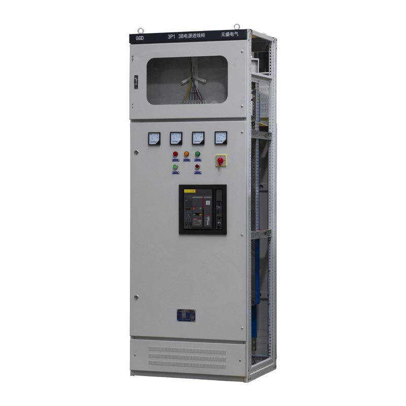
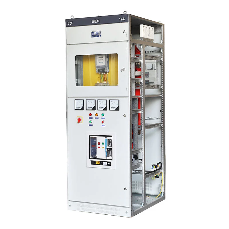
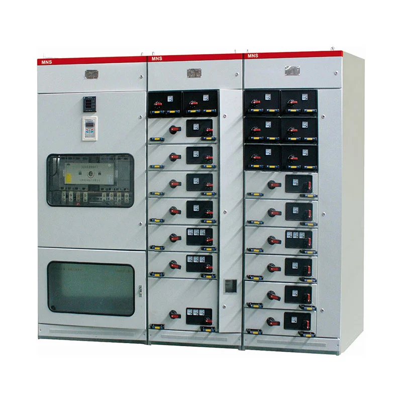
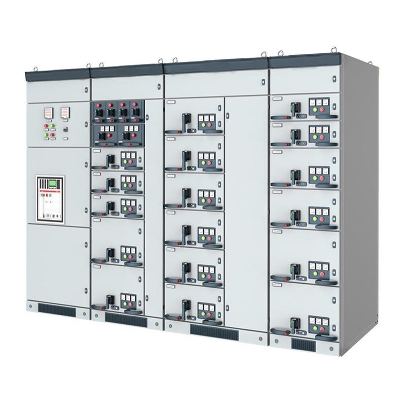
Low Voltage Drawer Type Switchgear Cabinet
  • Low Voltage Drawer Type Switchgear CabinetLow Voltage Drawer Type Switchgear Cabinet
  • Low Voltage Drawer Type Switchgear CabinetLow Voltage Drawer Type Switchgear Cabinet
  • Low Voltage Drawer Type Switchgear CabinetLow Voltage Drawer Type Switchgear Cabinet

Low Voltage Drawer Type Switchgear Cabinet

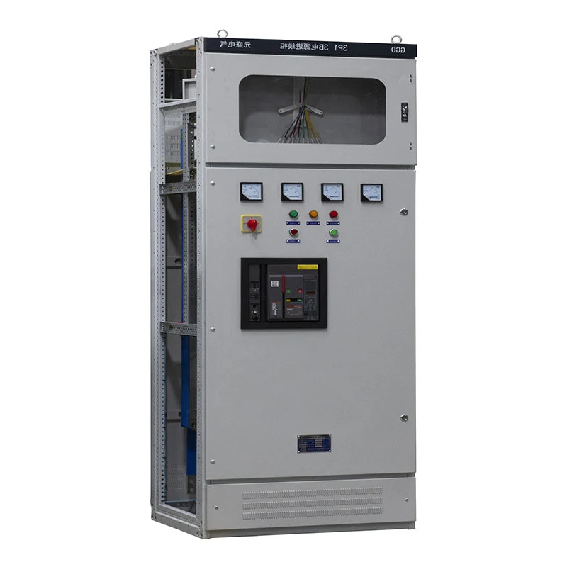
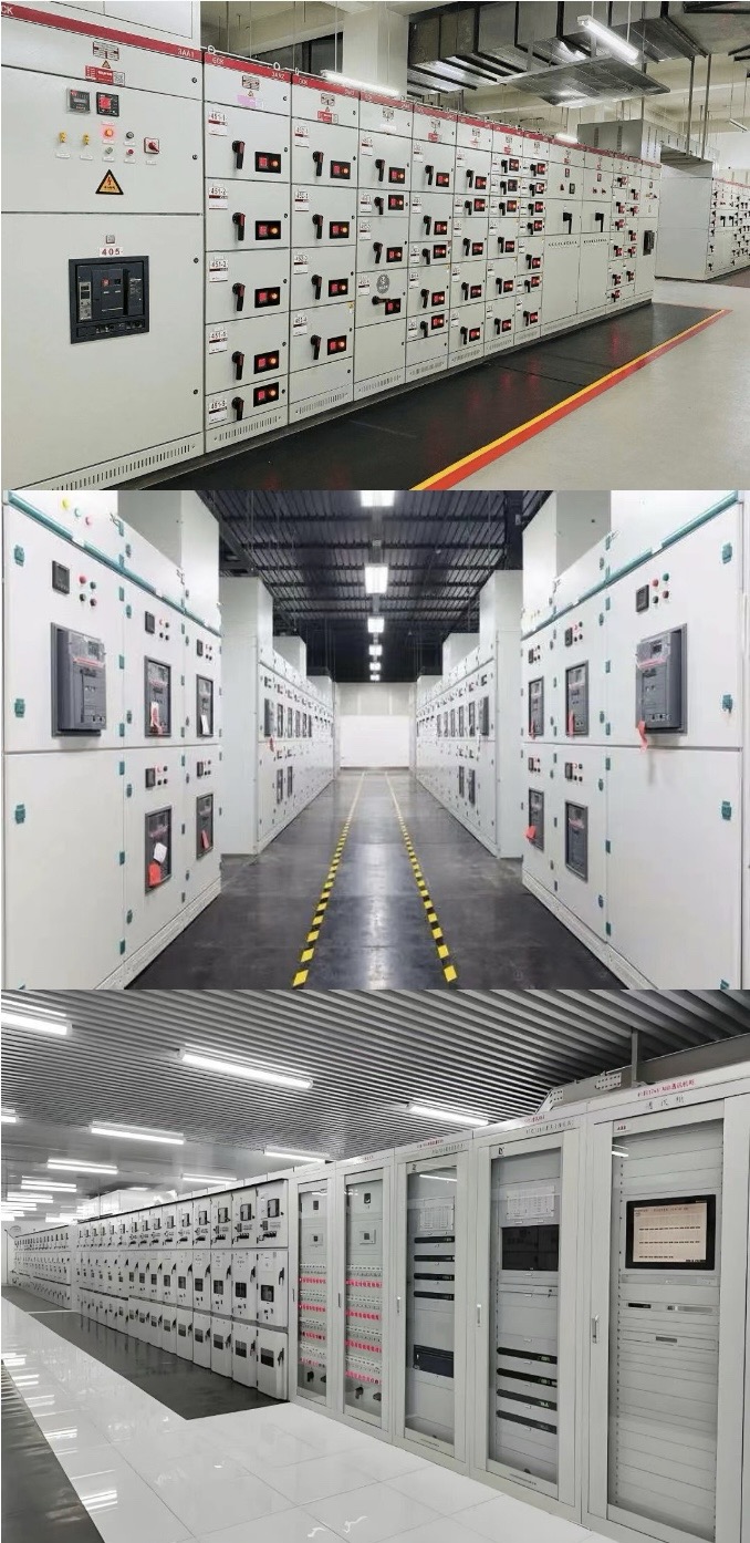
The Low Voltage Drawer Type Switchgear Cabinet from Zhejiang Usune Electric Co., Ltd. is developed around this requirement. Its drawer-based configuration separates individual functional circuits within a centralized cabinet, allowing different loads to be organized according to their electrical characteristics and operating requirements.

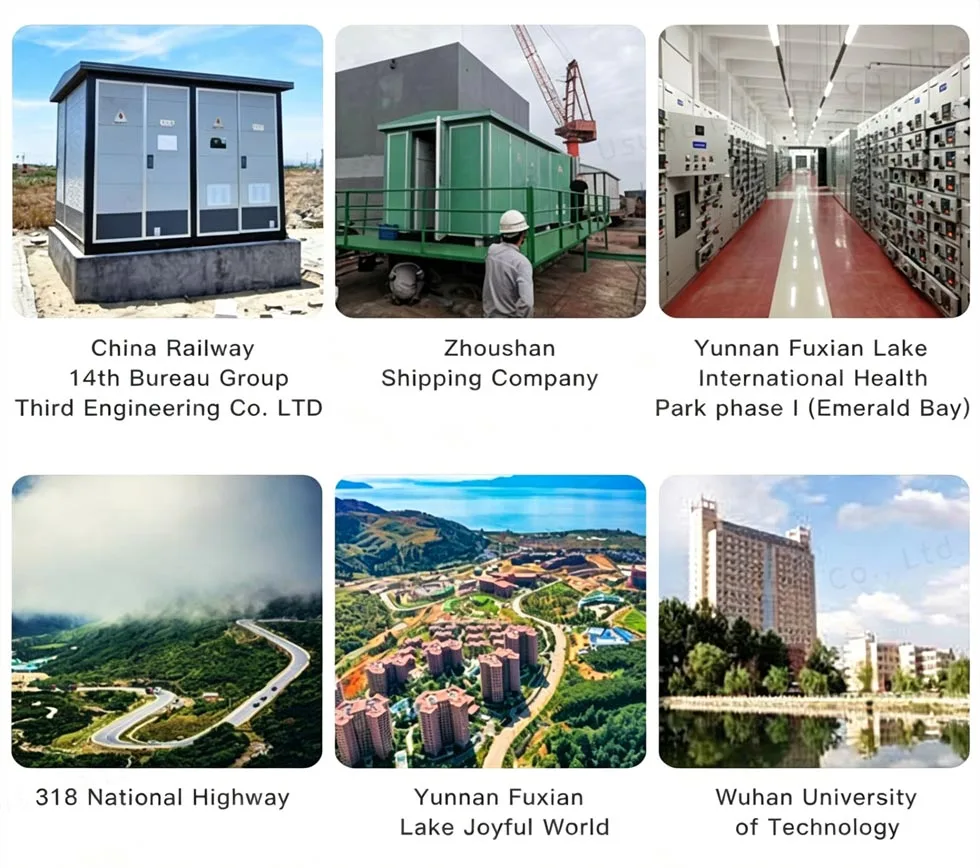
Designed for AC 50–60Hz systems with rated working voltage up to 660V, the Low Voltage Drawer Type Switchgear Cabinet can be configured for power distribution, motor control, and power factor compensation. It is suitable for industrial plants, power facilities, petrochemical projects, transportation infrastructure, commercial buildings, and other low-voltage electrical systems.

Low Voltage Drawer Type Switchgear Cabinet

Why Drawer Design Matters

In a conventional fixed distribution cabinet, electrical circuits are relatively dependent on the overall cabinet arrangement. When a facility contains many independent loads, this can make circuit management and future modification more complicated.

A drawer-type configuration divides electrical functions into individual units. Each drawer can correspond to a specific feeder, motor, or electrical load, allowing the overall cabinet to be organized according to the actual distribution structure.

For factories and large facilities, this means the switchgear can be planned around the electrical load rather than simply around the physical cabinet dimensions.

Circuit-by-Circuit Management

The drawer structure allows different circuits to be assigned to separate functional units.

For example, a production facility may have independent circuits for conveyor motors, pumps, fans, auxiliary machinery, lighting, and general power distribution. These circuits can be arranged according to their individual electrical requirements.

This structure helps operators identify the relationship between each circuit and its connected equipment, which is particularly valuable in large electrical rooms containing numerous outgoing feeders.

Different Loads, Different Drawers

Not every electrical load has the same power requirement. A small auxiliary motor and a high-power production motor may require different switching and protection arrangements.

The Low Voltage Drawer Type Switchgear Cabinet can therefore use large and small drawers for different circuit requirements. The drawer configuration can be determined according to motor ratings, feeder capacity, and the number of circuits within the project.

This provides electrical engineers with greater freedom when preparing the cabinet layout.

Motor Circuit Organization

For industrial facilities, motor control can account for a significant proportion of the low-voltage electrical system.

The MCC configuration is composed of large and small drawers, with the main switching device of each circuit using a high-breaking-capacity molded case circuit breaker or rotary load switch with fuse.

This arrangement can be applied to circuits serving pumps, compressors, fans, conveyors, production machinery, and other motor-driven equipment.

Separating these motor circuits into dedicated functional units also helps simplify the electrical relationship between individual motors and their corresponding feeders.

Power Distribution Arrangement

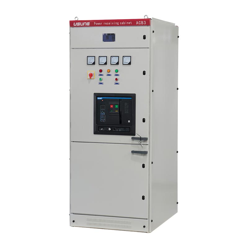
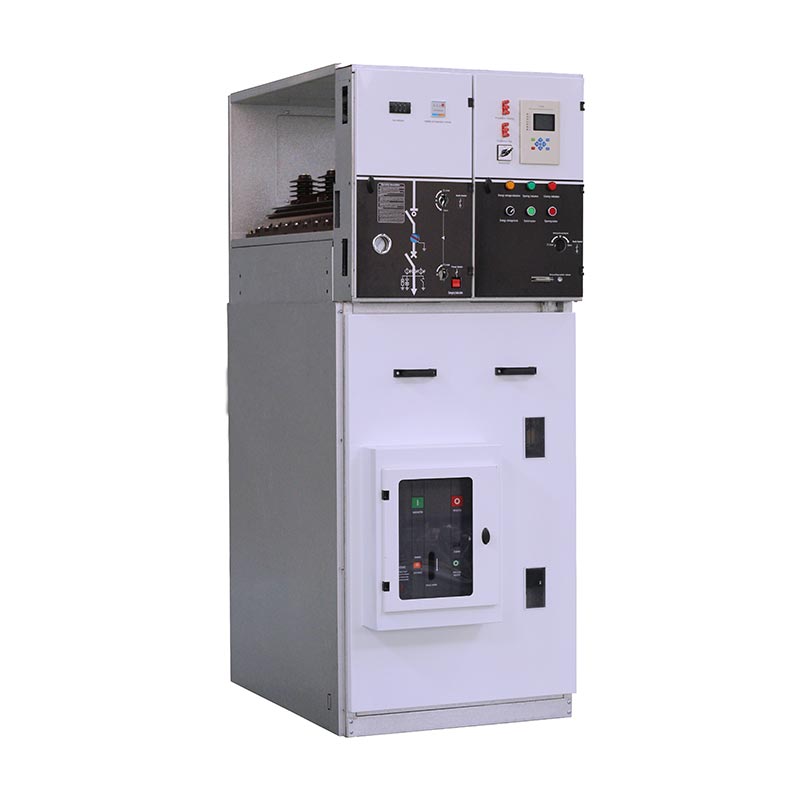
The Power Distribution Center cabinet is used where incoming electrical power needs to be divided among multiple downstream circuits.

The PC configuration can accommodate Emax, MT, 3WN, AH, and ME series circuit breakers, depending on the approved electrical design.

The selection should consider rated current, short-circuit capacity, feeder characteristics, protection coordination, and the requirements of the connected equipment.

Reactive Power Management

Motor-heavy industrial systems can generate significant reactive power demand. For such installations, power factor compensation may form part of the low-voltage electrical design.

The compensation cabinet can be configured for manual, automatic, or remote power factor compensation.

Its configuration can be determined according to the customer's load characteristics and electrical management requirements rather than using the same compensation arrangement for every project.

Where It Fits

The equipment can be adapted to electrical systems with different load structures.

Manufacturing Facilities

Factories with multiple production lines can use separate drawer units for motors, auxiliary equipment, and general power circuits.

Petrochemical Plants

Pumps, compressors, fans, and other process equipment can be arranged through dedicated motor control circuits.

Steel & Metallurgy

Large production facilities can use centralized low-voltage distribution for multiple high-power equipment and motor feeders.

Transportation Infrastructure

Railway facilities, terminals, and supporting infrastructure can use the cabinet for equipment power distribution and auxiliary electrical systems.

High-Rise Buildings

Commercial and residential buildings can organize multiple low-voltage feeders within a centralized distribution system.

Energy Facilities

Power plants and energy projects can configure distribution, motor control, and compensation functions according to their auxiliary electrical loads.

Low Voltage Drawer Type Switchgear CabinetLow Voltage Drawer Type Switchgear Cabinet

Technical Data

Item Specification
Product Type Low-Voltage Drawer Type Switchgear
Rated Working Voltage ≤660V
Rated Frequency 50Hz / 60Hz
Main Functions Power Distribution / Motor Control / Power Factor Compensation
PC Configuration Emax / MT / 3WN / AH / ME Series Circuit Breakers
MCC Configuration Large and Small Drawers
MCC Main Switching High-Breaking MCCB / Rotary Load Switch with Fuse
Compensation Manual / Automatic / Remote
Standard Altitude ≤2000m
Ambient Temperature -5°C to +40°C
24-Hour Average Temperature ≤+35°C
Transport & Storage -25°C to +55°C
Short-Term Temperature Up to +70°C for ≤24h
Applicable Frequency AC 50–60Hz

Working Environment

The standard operating environment should have an ambient temperature between -5°C and +40°C, with an average temperature over 24 hours not exceeding +35°C.

At a maximum ambient temperature of +40°C, relative humidity should not exceed 50%. Higher humidity may be acceptable at lower temperatures, such as up to 90% at +20°C. Temperature variations should be considered because condensation may occur.

The standard altitude is ≤2000m.

During transportation and storage, the equipment can withstand temperatures from -25°C to +55°C, with short-term exposure up to +70°C for a period not exceeding 24 hours.

Special applications, including offshore oil drilling platforms and nuclear power plants, require separate technical evaluation and agreement between the manufacturer and final user.

Project Reference

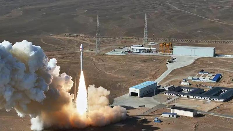
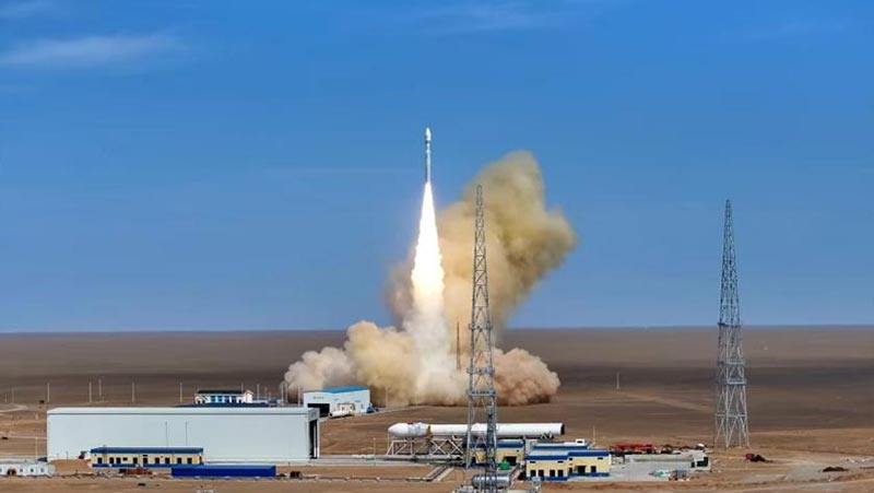
Cas-space Rocket Launch Project

The Cas-space Rocket Launch Project is an engineering reference for Usune electrical equipment.

Rocket launch infrastructure contains various supporting electrical loads, including equipment systems, auxiliary facilities, and infrastructure services. Such facilities require clear circuit organization and dependable electrical distribution to support different operational areas.

Usune equipment was applied as part of the project's electrical system, providing practical experience in supplying switchgear for specialized infrastructure.

The project also demonstrates the importance of adapting cabinet configuration to the actual electrical architecture of a facility rather than relying on a uniform arrangement.

Project ReferenceProject Reference

Quality & Compliance

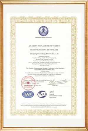
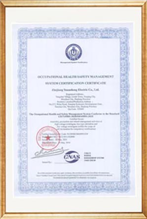
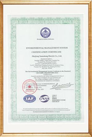
Usune's production and management system is supported by ISO 9001, ISO 14001, and ISO 45001.

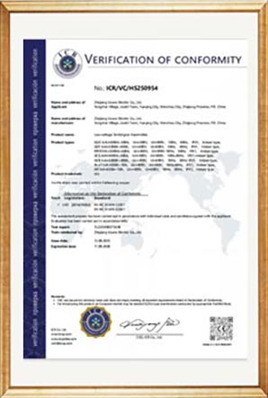
The equipment is manufactured according to applicable IEC and GB requirements, including GB 7251.1, JB/T 9961, and relevant international requirements for low-voltage switchgear and controlgear assemblies.

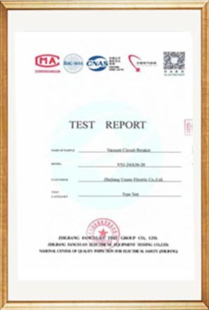
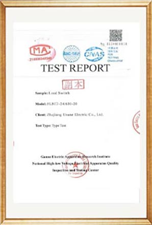
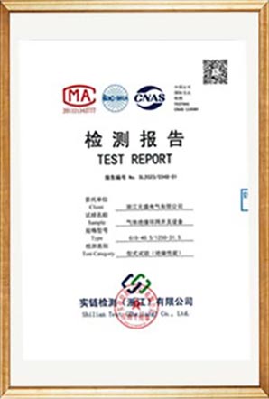
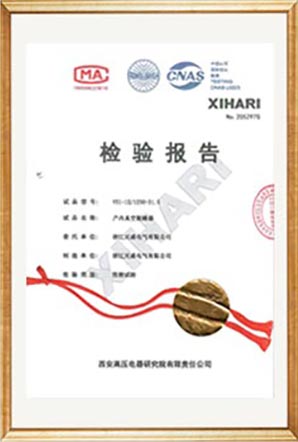
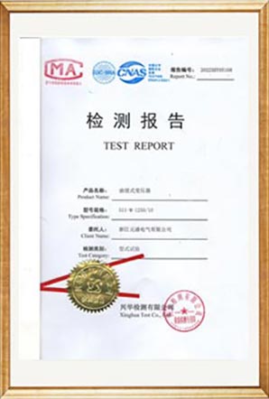
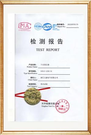
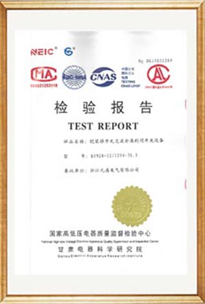
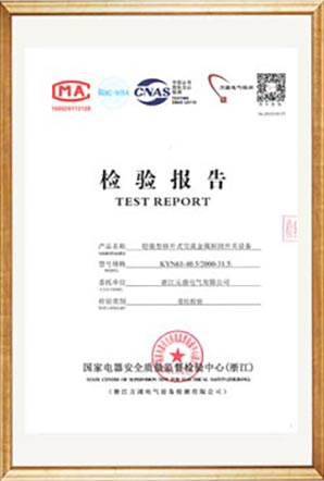
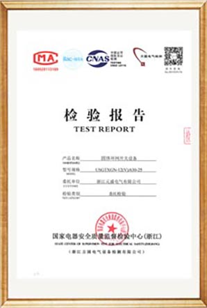
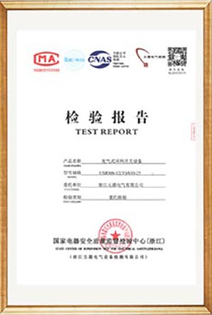
Before shipment, the finished cabinet undergoes factory inspection and routine testing. Relevant test reports and technical documentation can be supplied according to project requirements.

Test ReportTest ReportTest ReportTest ReportTest ReportTest ReportTest ReportTest ReportTest ReportTest ReportTest ReportTest ReportTest ReportTest ReportTest Report

Configuration Before Purchase

For procurement teams, the most important step is confirming the electrical configuration before manufacturing.

A Low Voltage Drawer Type Switchgear Cabinet should be selected according to the actual load list rather than only the cabinet's rated voltage.

Usune recommends confirming:

Customer Information Why It Matters
System Voltage Determines basic electrical design
Incoming Current Determines incoming capacity
Number of Feeders Determines drawer quantity
Motor Quantity Determines MCC requirements
Motor Ratings Determines drawer and switching selection
Short-Circuit Level Determines protection requirements
Compensation Requirement Determines compensation capacity
Installation Environment Confirms operating conditions
Single-Line Diagram Supports final cabinet configuration

Providing these details during the quotation stage allows Usune to prepare a configuration that better matches the customer's actual electrical system.

Product External Dimension

Low Voltage Drawer Type Switchgear Cabinet

A power distribution center(PC) cabinet

N o. Items Unit Load break switch unit combination unit Circuit breaker unit
1 Rated voltage kV 12/24 12/24 12/24
2 Rated frequency Hz 50 50 50
3 Rated current A 630 125 (depends on fuse current) 630
4 Rated insulation level 1min Frequency withstood pressure kV 42/65 42/65 42/65
48/79 48/79 48/79
2/2 2/2 2/2
Lighting impulse withstood voltage 75/125 75/125 75/125
85/145 85/145 85/145
5 Rated short circuit withstand current kA/s 25/4 —— 25/4
6 Rated peak withstand current kA 63 —— 63
7 Rated short circuit making current kA 63 Limited by HV fuse 63
8 Rated short circuit breaking current kA —— Limited by HV fuse 25/25
9 Rated transmission current A —— 1700/1400 ——
10 Rated active load breaking current A 630 —— ——
11 Rated closed‑loop breaking current A 630 —— 630
12 Mechanical life load break switch/CB Times 10000 10000 20000
Isolation/ground switch 5000 5000 5000
13 Circuit resistance μΩ ≤150 —— ≤150
14 Rated charging pressure (20℃ gauge pressure) MPa 0.04 0.04 0.04
15 Gas annual relative leakage rate % 0.05 0.05 0.05
16 IP protection degree Cabinet IP4X IP4X IP4X
Gas tank IP67 IP67 IP67

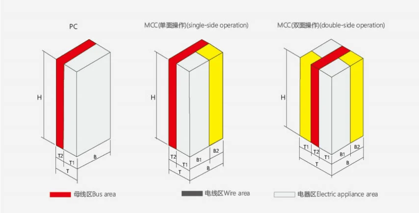
B Motor control center(MCC) cabinet

Height Width Depth Note
H B B1 B2 T T1 T2
2200 1000 600 400 600 400 200 Single‑side operation
2200 1000 600 400 1000 400 200 Double‑side operation

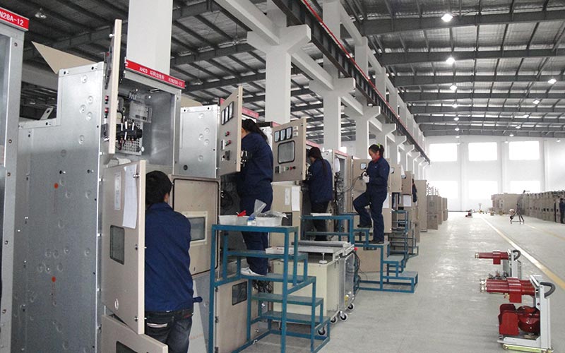
Factory Production

The cabinet is assembled at the factory using standardized cabinet structures and functional components.

The production process covers component inspection, structural assembly, drawer installation, electrical wiring, functional-unit inspection, and routine testing.

This factory-based assembly process allows the final cabinet configuration to be checked against the approved technical requirements before shipment.

FAQ

What voltage can the cabinet handle?

The equipment is designed for AC systems with rated working voltage of 660V and below.

Why use a drawer-type configuration?

The drawer arrangement allows individual electrical circuits to be organized as separate functional units, which can make large distribution systems easier to manage and configure.

Can large and small drawers be combined?

Yes. The MCC configuration can use both large and small drawers according to motor capacity and circuit requirements.

What equipment can be installed in the PC cabinet?

The PC configuration can use Emax, MT, 3WN, AH, and ME series circuit breakers according to the approved project design.

Is it suitable for motor control?

Yes. The MCC section is specifically designed for multiple motor circuits and can be configured with different drawer sizes.

Does it support power factor compensation?

Yes. Manual, automatic, and remote compensation functions can be configured according to project requirements.

What certifications does Usune have?

Usune operates under ISO 9001, ISO 14001, and ISO 45001 management systems. Products are manufactured according to applicable IEC and GB standards, with CE certification available for applicable configurations.

Can Usune customize the cabinet?

Yes. Drawer quantity, circuit arrangement, breaker selection, MCC configuration, and compensation functions can be determined according to the customer's electrical requirements.

What information should be provided for a quotation?

The most useful information includes system voltage, incoming current, number of feeders, motor quantity and ratings, short-circuit level, compensation requirements, installation environment, and the electrical single-line diagram.

Usune Project Support

Usune provides low-voltage switchgear for electrical systems where multiple power circuits need to be organized within a centralized cabinet.

For customers sourcing a Low Voltage Drawer Type Switchgear Cabinet, Usune can evaluate the electrical load structure, select suitable drawer configurations, coordinate component selection, complete factory assembly and testing, and provide technical documentation for project delivery.

Hot Tags: Low Voltage Drawer Type Switchgear Cabinet, China, Manufacturer, Supplier, Factory
Send Inquiry
Contact Info
If you have any inquiry about a quotation or cooperation, please feel free to email or use the following inquiry form. Our sales representative will contact you within 24 hours.
X
We use cookies to offer you a better browsing experience, analyze site traffic and personalize content. By using this site, you agree to our use of cookies.Privacy Policy
RejectAccept