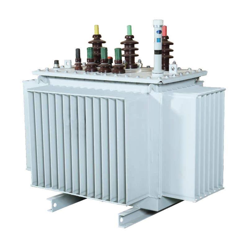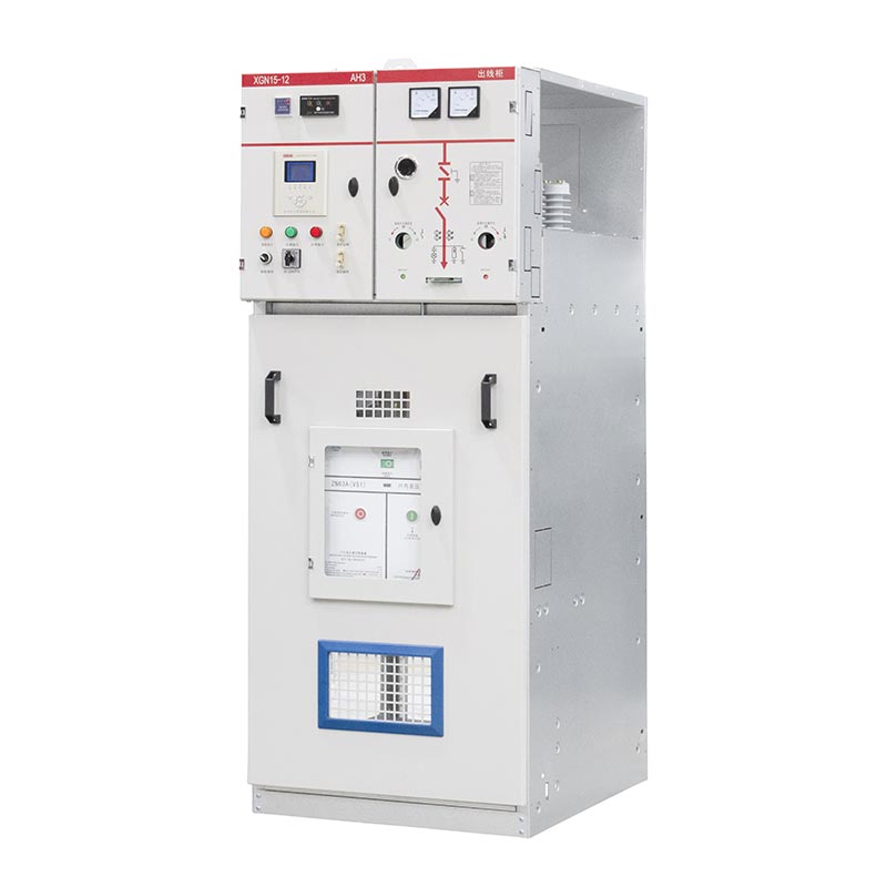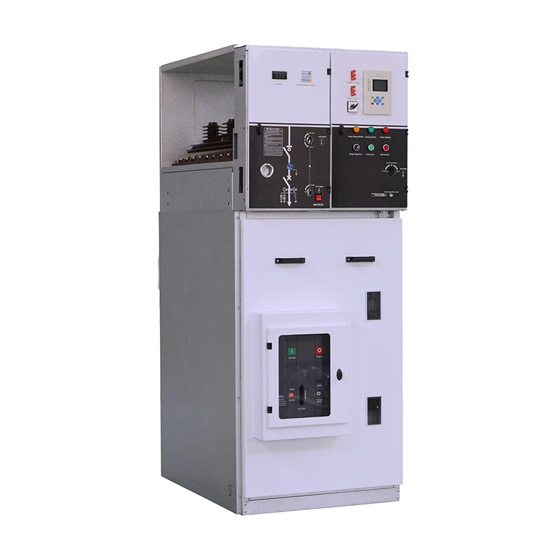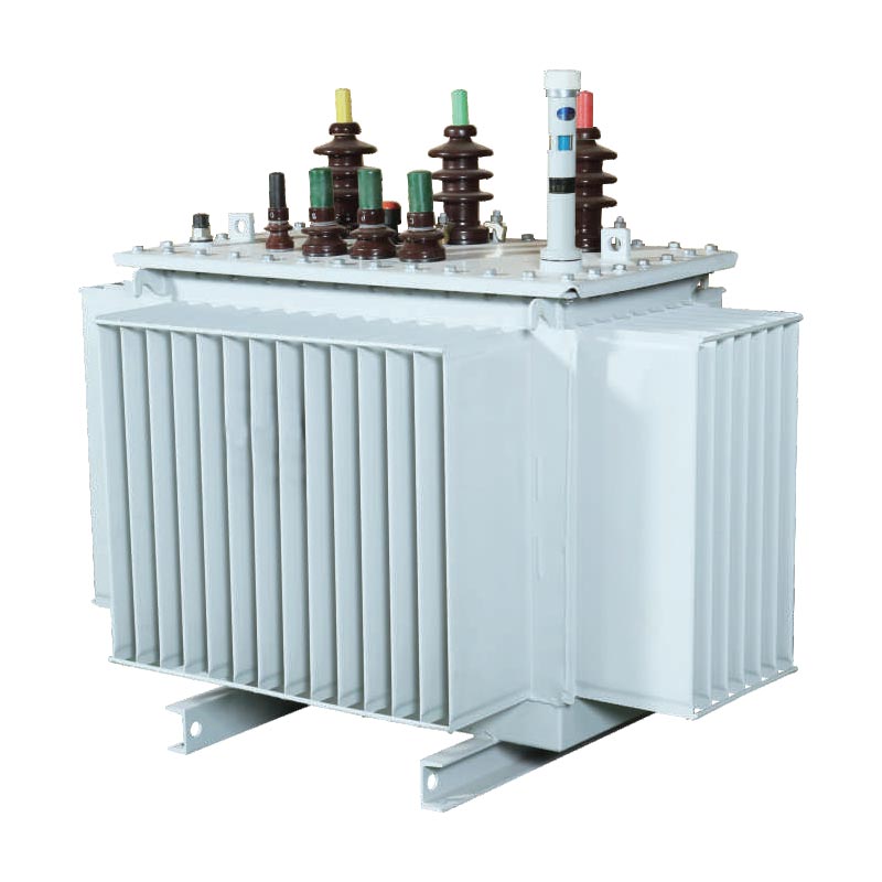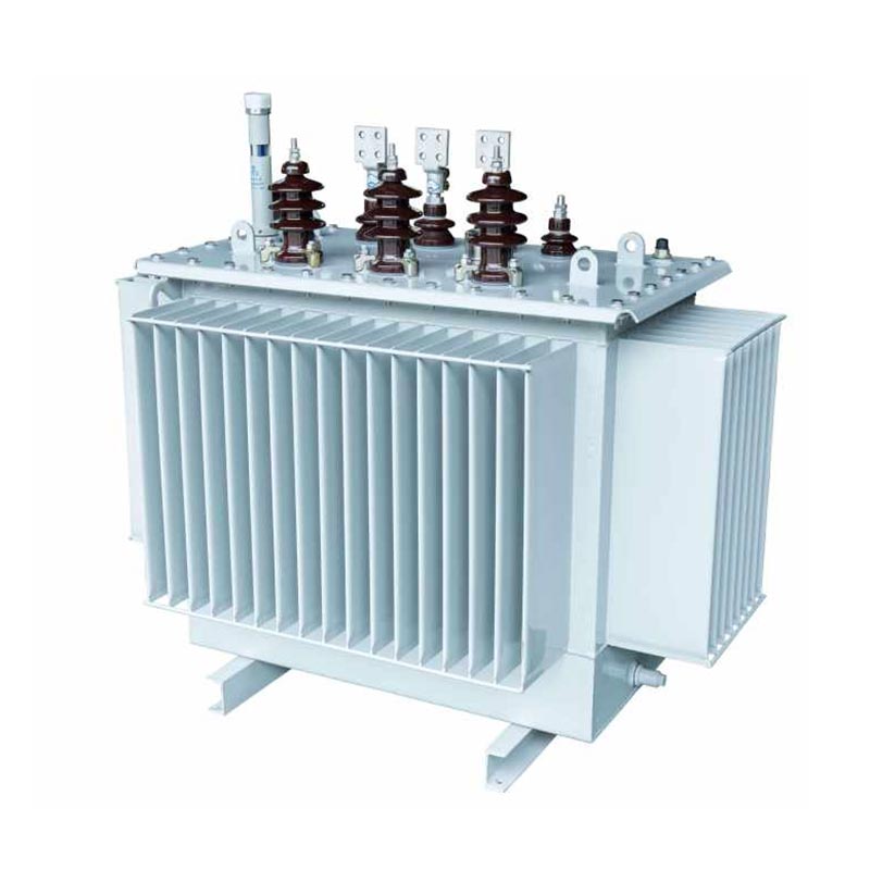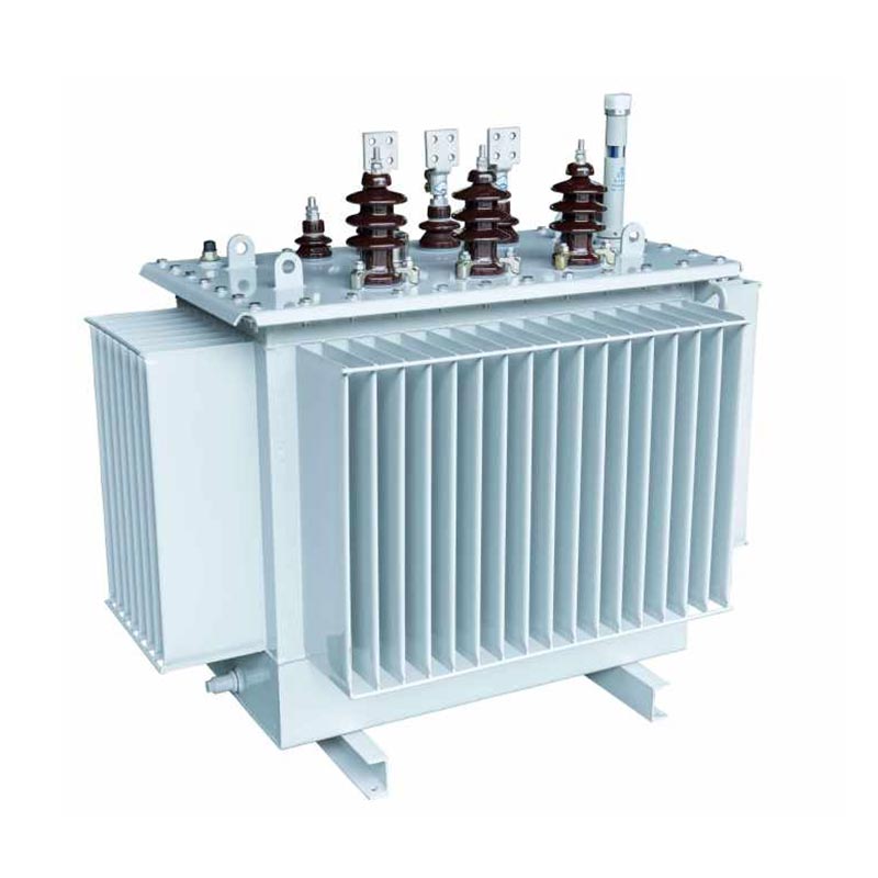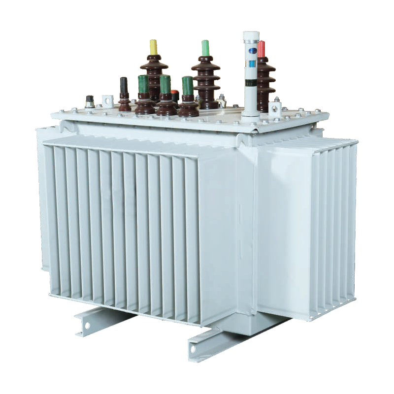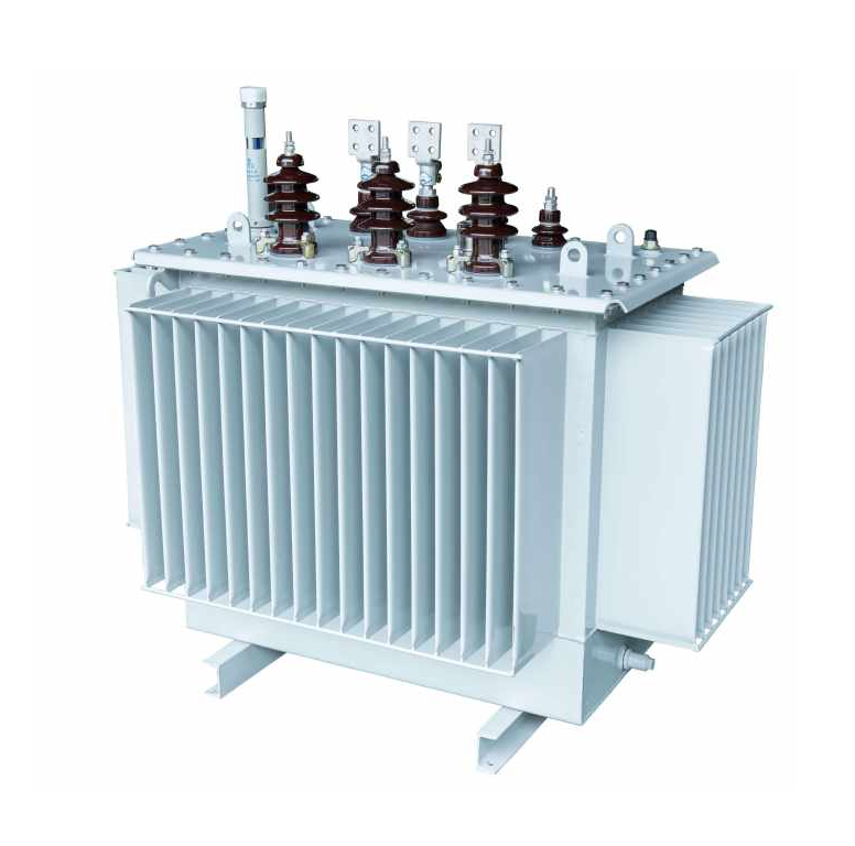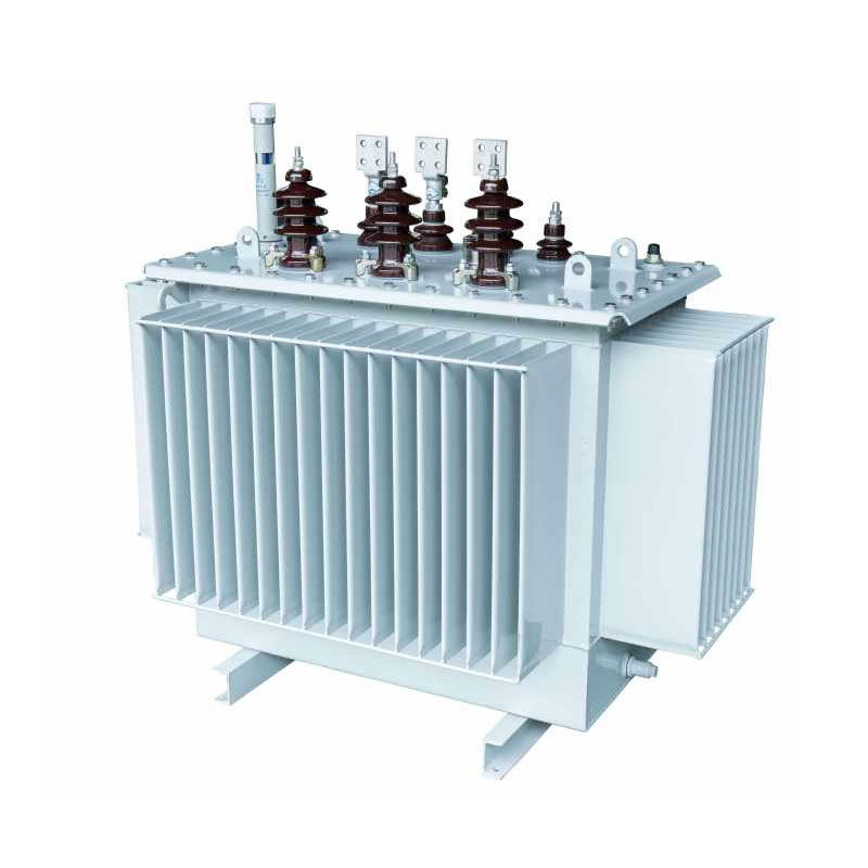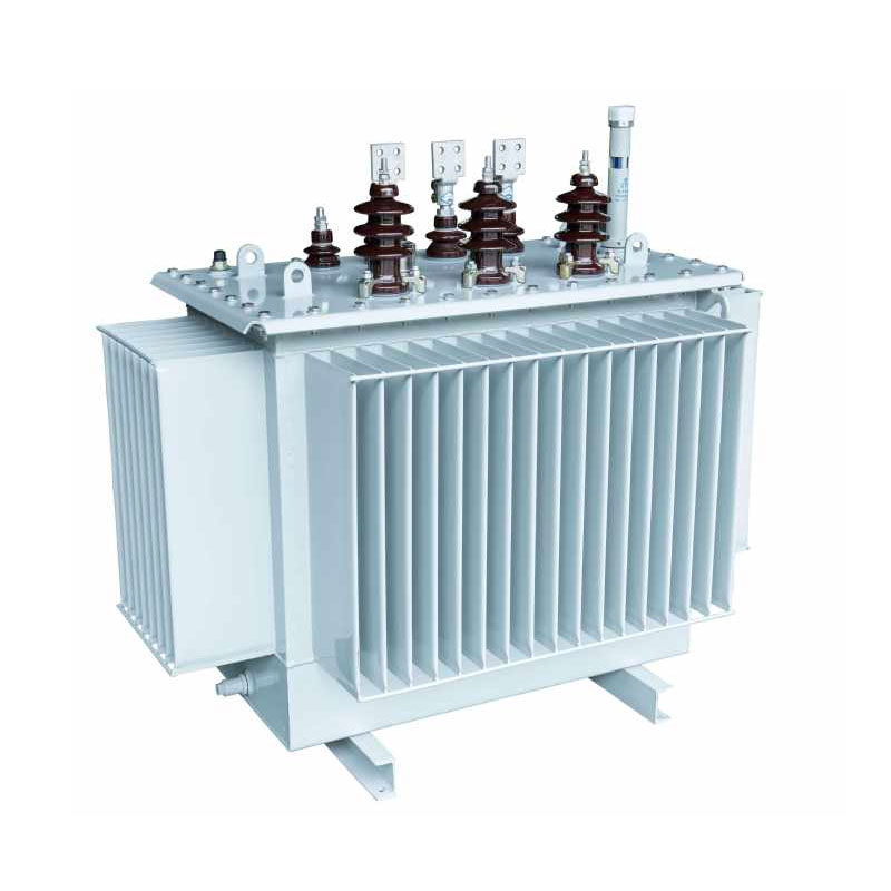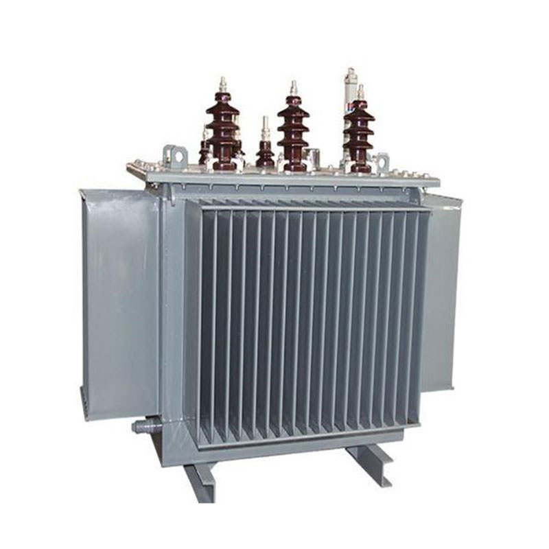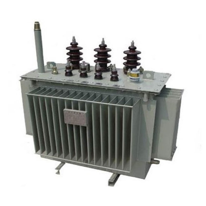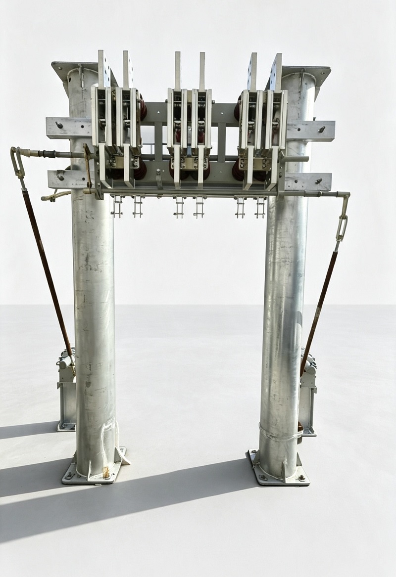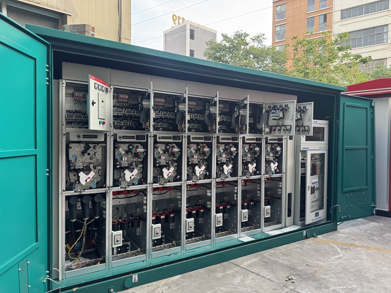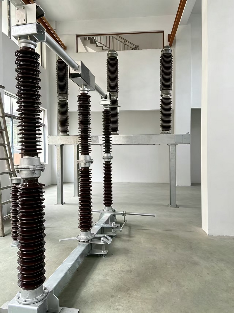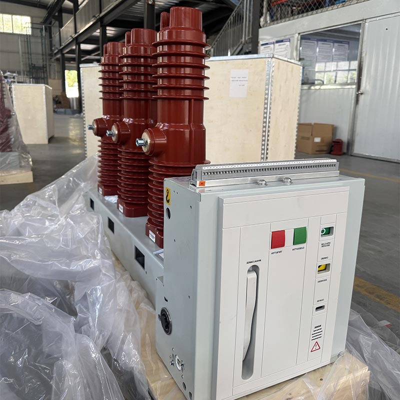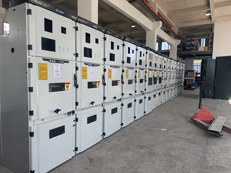
The USUNE 3 Phase Onan Distribution Transformer (ONAN) is independently developed and manufactured by USUNE, a professional manufacturer integrating R&D, production, and sales. It is specifically designed for the power distribution needs of modern urban and rural areas and industrial and mining enterprises, solving problems such as low efficiency, high energy consumption, and poor stability of traditional transformers. The product is manufactured in USUNE's standardized factory, relying on a strict quality control system to ensure that each piece of equipment meets international industry standards and can operate stably under various harsh operating conditions.
The 3 Phase Onan Distribution Transformer employs a three-dimensional wound core with an equilateral triangular arrangement, eliminating air gaps in the magnetic circuit, resulting in tighter windings and the shortest possible three-phase magnetic circuit length. The core column cross-sectional area is nearly circular, optimizing the magnetic circuit structure, reducing energy consumption and operating noise, achieving three-phase balance, and reducing third harmonic components, laying the foundation for efficient and stable power supply.
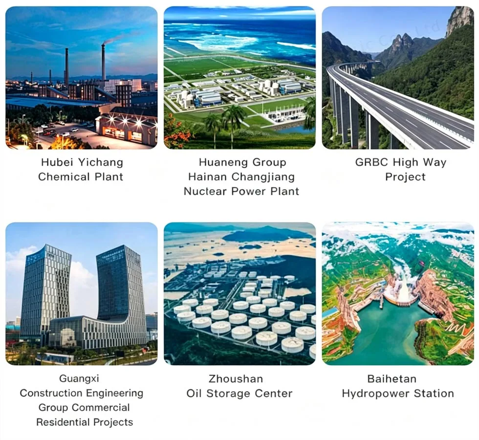
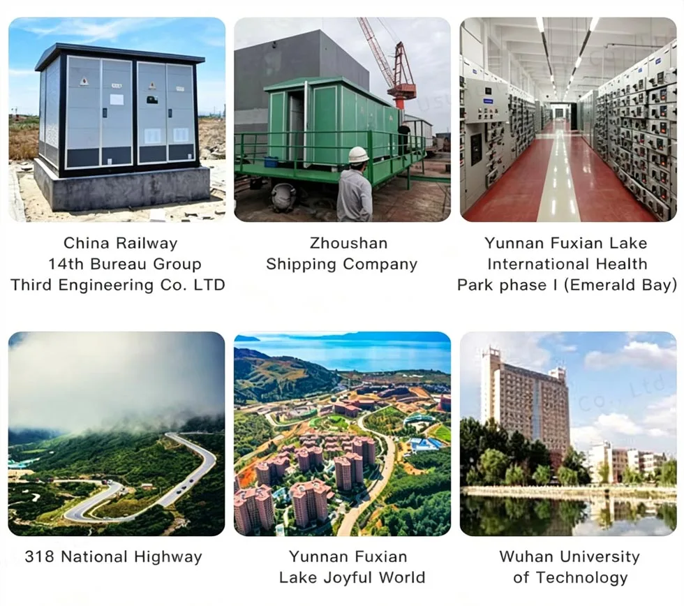
This product is suitable for urban and rural power grid upgrades and industrial and mining enterprise scenarios, and can be perfectly matched with modular and prefabricated substations, providing reliable power supply support. As a professional power equipment supplier, USUNE has extensive R&D and manufacturing experience and can provide customized solutions according to customer needs.

The 3 Phase Onan Distribution Transformer uses high-quality grain-oriented silicon steel sheets with excellent magnetic permeability and low losses; it uses a German GEORG cross-cutting machine with 45° seam cutting to ensure core precision and reduce magnetic leakage; the silicon steel sheets are folded into multi-stage circular cross-sections, optimizing the magnetic circuit, reducing noise and power consumption, and improving energy efficiency.
The high-voltage coil is cylindrical, while the low-voltage coil is cylindrical or foil-type, effectively improving short-circuit and lightning strike resistance. The coil design is rational, with uniform magnetic circuit distribution, reducing localized overheating, extending service life, and ensuring stable operation.
Made of high-quality precision cold-rolled steel plate, manufactured using the German GEORG corrugated oil tank production line, ensuring structural strength and sealing. The surface is coated with an anti-corrosion coating, suitable for harsh environments such as petrochemical plants, meeting environmental protection requirements. The corrugated structure combines heat dissipation and adaptability to oil thermal expansion and contraction, while the sealed design slows oil aging and extends transformer life.
The 3 Phase Onan Distribution Transformer adopts a Class A insulation structure with excellent insulation performance, capable of withstanding high-voltage impacts. The high and low voltage coils are arranged concentrically, and the coil spacing uses a cardboard sleeve with a small oil gap to improve insulation performance, prevent short circuits, and ensure safe and stable operation.
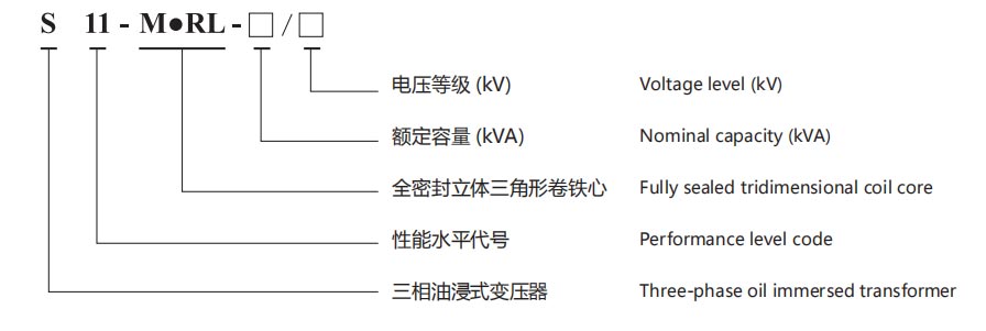
The USUNE 3 Phase Onan Distribution Transformer (ONAN) covers three voltage levels: 10KV, 20KV, and 36KV, meeting various power distribution needs. It can be customized according to the customer's actual load, core specifications, and installation scenario, providing flexible solutions.
1. Electricity Cost (RMB/Year) = [No-load Loss (kW) + Load Loss (kW) × (Average Load Rate)²] × 365 (Days) × 24
(Hours) ×
Electricity Price
2. CO2 Emissions = [No-load Loss (kW) + Load Loss (kW) × (Average Load Rate)²] × 365 (Days) × 24 (Hours) × Emission
Factor (kg-CO₂/kWh)
The product's no-load and load losses are significantly lower than traditional transformers, significantly reducing users' electricity costs and CO2 emissions. As a manufacturer rooted in China, USUNE adheres to the concept of green development, continuously optimizes product design, and promotes the sustainable development of the power industry.
1. Urban and Rural Power Grid Upgrading: Improves power grid stability and efficiency, solving problems of insufficient power supply and high energy consumption.
2. Industrial and Mining Enterprises: Meets the demand for high-power, stable power supply, withstands harsh environments, and ensures the operation of production equipment.
3. Modular and Prefabricated Substations: Compact structure, convenient installation and maintenance, reducing land area and construction costs.
| Nominal capacity (kVA) | HV (kV) | High voltage tapping range | LV (kV) | Vector group | No-load loss (kW) | load loss (kW) | No-load current (%) | Impedance (%) | Total weight (kg) | L×W×H (mm) | Installation center / installation hole (mm) |
| 30 |
6 6.3 10 10.5 11 |
±5% ±2×2.5% |
0.4 |
Yyn0 Dyn11 |
100 | 630/600 | 1.8 | 4.0 | 335 | 1030×690×860 | 400x400/4xφ14 |
| 50 | 130 | 910/870 | 1.6 | 410 | 1045×700×925 | 400x400/4×φ14 | |||||
| 63 | 150 | 1090/1040 | 1.5 | 460 | 1075×710×940 | 400x400/4×φ14 | |||||
| 80 | 180 | 1310/1250 | 1.4 | 490 | 1080×715×995 | 400×400/4×φ19 | |||||
| 100 | 200 | 1580/1500 | 1.3 | 550 | 1110×730×1020 | 40×400(50)14×019 | |||||
| 125 | 240 | 1890/1800 | 1.2 | 615 | 1135×740×1035 | 40x×400(50)4×019 | |||||
| 160 | 280 | 2310/2200 | 1.1 | 695 | 1155×755×1050 | 550×550/4×φ19 | |||||
| 200 | 340 | 2730/2600 | 1 | 790 | 1200×770×1075 | 550×550/4×φ19 | |||||
| 250 | 400 | 3200/3050 | 0.9 | 930 | 1240×800×1100 | 550×550/4xφ19 | |||||
| 315 | 480 | 3830/3650 | 0.8 | 1110 | 1305×840×1120 | 550×550/4×φ19 | |||||
| 400 | 570 | 4520/4300 | 0.7 | 1290 | 1390×900×1160 | 660×660/4xφ19 | |||||
| 500 | 680 | 5410/5150 | 0.7 | 1510 | 1500×990×1195 | 660×660/4×φ19 | |||||
| 630 | 810 | 6200 | 0.6 | 4.5 | 1730 | 1580×1030×1305 | 660×660/4xφ19 | ||||
| 800 | 980 | 7500 | 0.6 | 2075 | 1705×1140×1360 | 820×820/4×φ19 | |||||
| 1000 | 1150 | 10300 | 0.5 | 2490 | 1730×1290×1395 | 820×820/4×φ19 | |||||
| 1250 | 1360 | 12000 | 0.4 | 2960 | 1780×1320×1480 | 820×820/4×φ19 | |||||
| 1600 | 1640 | 14500 | 0.4 | 3515 | 1890×1430×1520 | 820×820/4×φ19 | |||||
| 2000 | 1940 | 18300 | 0.4 | 5 | 4880 | 2050×1360×1840 | 820×820/4×φ19 | ||||
| 2500 | 2290 | 21200 | 0.4 | 6010 | 2170×1430×2015 | 1070×1070/4×φ19 |
Note: For transfomers with rated capacity of 500 kVA and below,the load loss above the ramp in the table is applicable to the Dyn11 connection group,and the load loss below the ramp is applicable to the Yyn0 connection group.
| Nominal capacity (kVA) | HV (kV) | High voltage tapping range | LV (kV) | Vector group | No-load loss (kW) | load loss (kW) | No-load current (%) | Impedance (%) | Total weight (kg) | L×W×H (mm) | Installation center / installation hole (mm) |
| 30 |
6 6.3 10 10.5 11 |
±5% ±2×2.5% |
0.4 |
Yyn0 Dyn11 |
80 | 630/600 | 1.8 | 4.0 | 345 | 1175×685×925 | 400×400/4xφ14 |
| 50 | 100 | 910/870 | 1.6 | 430 | 1190×700×985 | 400×400/4xφ14 | |||||
| 63 | 110 | 1090/1040 | 1.5 | 500 | 1210×710×1015 | 400×400/4xφ14 | |||||
| 80 | 130 | 1310/1250 | 1.4 | 570 | 1240×730×1080 | 400×400/4xφ19 | |||||
| 100 | 150 | 1580/1500 | 1.3 | 590 | 1255×730×1095 | 400×400(550)4×Q19 | |||||
| 125 | 170 | 1890/1800 | 1.2 | 675 | 1300×740×1255 | 400×400(50)4×Q19 | |||||
| 160 | 200 | 2310/2200 | 1.1 | 755 | 1330×760×1275 | 550×550/4xφ19 | |||||
| 200 | 240 | 2730/2600 | 1 | 870 | 1360×770×1300 | 550×550/4xφ19 | |||||
| 250 | 290 | 3200/3050 | 0.9 | 1035 | 1390×800×1340 | 550×550/4xφ19 | |||||
| 315 | 340 | 3830/3650 | 0.8 | 1200 | 1440×820×1375 | 550×550/4xφ19 | |||||
| 400 | 410 | 4520/4300 | 0.7 | 1390 | 1470×830×1415 | 660×660/4xφ19 | |||||
| 500 | 480 | 5410/5150 | 0.7 | 1590 | 1545×950×1445 | 660×660/4xφ19 | |||||
| 630 | 570 | 6200 | 0.6 | 4.5 | 1950 | 1650×1000×1565 | 660×660/4xφ19 | ||||
| 800 | 700 | 7500 | 0.6 | 2375 | 1975×1060×1690 | 820×820/4xφ19 | |||||
| 1000 | 830 | 10300 | 0.5 | 2685 | 2160×1240×1725 | 820×820/4×φ19 | |||||
| 1250 | 970 | 12000 | 0.4 | 3110 | 2200×1260×1820 | 820×820/4xφ19 | |||||
| 1600 | 1170 | 14500 | 0.4 | 3800 | 2260×1320×1890 | 820×820/4xφ19 | |||||
| 2000 | 1550 | 18300 | 0.4 | 5 | 5005 | 2540×1290×2225 | 820×820/4xφ19 | ||||
| 2500 | 1830 | 21200 | 0.4 | 6310 | 2625×1360×2395 | 1070×1070/4×φ19 |
| Nominal capacity (kVA) | HV (kV) | High voltage tapping range | LV (kV) | Vector group | No-load loss (kW) | load loss (kW) | No-load current (%) | Impedance (%) | Total weight (kg) | L×W×H (mm) | Installation center / installation hole (mm) |
| 30 |
6 6.3 10 10.5 11 |
±5% ±2×2.5% |
0.4 |
Yyn0 Dyn11 |
80 | 505/480 | 1.8 | 4.0 | 390 | 1210×705×935 | 400×400/4×φ14 |
| 50 | 100 | 730/695 | 1.6 | 495 | 1255×715×1020 | 400×400/4×φ14 | |||||
| 63 | 110 | 870/830 | 1.5 | 540 | 1240×725×1045 | 400×400/4×φ14 | |||||
| 80 | 130 | 1050/1000 | 1.4 | 620 | 1270×740×1105 | 400×400/4×φ19 | |||||
| 100 | 150 | 1265/1200 | 1.3 | 685 | 1295×750×1120 | 40×40(550)14×019 | |||||
| 125 | 170 | 1510/1440 | 1.2 | 775 | 1345×760×1285 | 40×400(550)14×019 | |||||
| 160 | 200 | 1850/1760 | 1.1 | 890 | 1360×780×1325 | 550×550/4×φ19 | |||||
| 200 | 240 | 2185/2080 | 1 | 1005 | 1415×790×1340 | 550×550/4×φ19 | |||||
| 250 | 290 | 2560/2440 | 0.9 | 1130 | 1450×810×1360 | 550×550/4×φ19 | |||||
| 315 | 340 | 3065/2920 | 0.8 | 1320 | 1495×830×1410 | 550×550/4×φ19 | |||||
| 400 | 410 | 3615/3440 | 0.7 | 1445 | 1510×840×1435 | 660×660/4×φ19 | |||||
| 500 | 480 | 4330/4120 | 0.7 | 1735 | 1555×855×1495 | 660×660/4×φ19 | |||||
| 630 | 570 | 4960 | 0.6 | 4.5 | 2080 | 1655×905×1610 | 660×660/4×φ19 | ||||
| 800 | 700 | 6000 | 0.6 | 2465 | 1960×910×1725 | 820×820/4×φ19 | |||||
| 1000 | 830 | 8240 | 0.5 | 2755 | 2060×1210×1765 | 820×820/4×φ19 | |||||
| 1250 | 970 | 9600 | 0.4 | 3480 | 1590×1120×1940 | 820×820/4×φ19 | |||||
| 1600 | 1170 | 11600 | 0.4 | 4110 | 1670×1180×1770 | 820×820/4×φ19 | |||||
| 2000 | 1550 | 14640 | 0.4 | 5 | 5610 | 2240×1140×2495 | 820×820/4×φ19 | ||||
| 2500 | 1830 | 16960 | 0.4 | 6735 | 2315×1210×2670 | 1070×1070/4×φ19 |


Factory, we can guarantee our price is reasonable and competitive.
Usually we quote within 24 hours after receiving your inquiry.
Yes, of course, we accept OEM.
The lead time depends on the quantities ordered, normally within 15-20 days after receiving the payment.
All products will be inspected starting from accessories, and will be carried out with routine tests before leaving our factory.
Take photos or video of the quality problems and send to us for our checking and confirming, and we will make a satisfied solution for you within 1-3 days.
12 months from shipping date.
● We are specialized in the field for more than 14 years, and has a well experienced R&D team taking the design
and development work for each project based on customer's special demands.
● We have extremely strict QC procedure from components to finished products.
● Steady production period within 15-20 days.
● We have full set of test reports for products.
● One step solution provided.
Address
No. 298, Wei 17th Road, Yueqing Economic Development Zone, Yueqing, Wenzhou City, Zhejiang Province, China
Tel