Products

Products

Low Voltage Switchgear
  • Low Voltage SwitchgearLow Voltage Switchgear
  • Low Voltage SwitchgearLow Voltage Switchgear
  • Low Voltage SwitchgearLow Voltage Switchgear

Low Voltage Switchgear

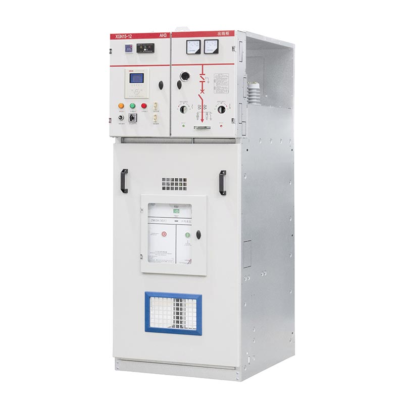
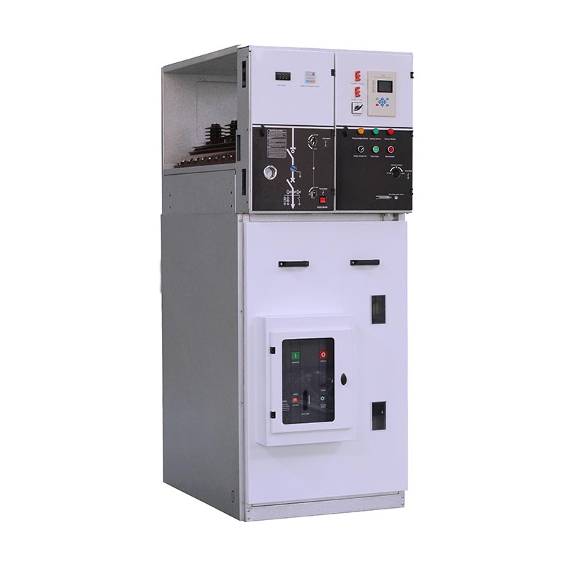
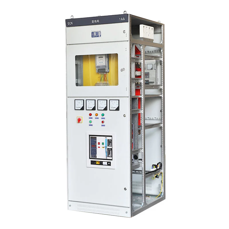
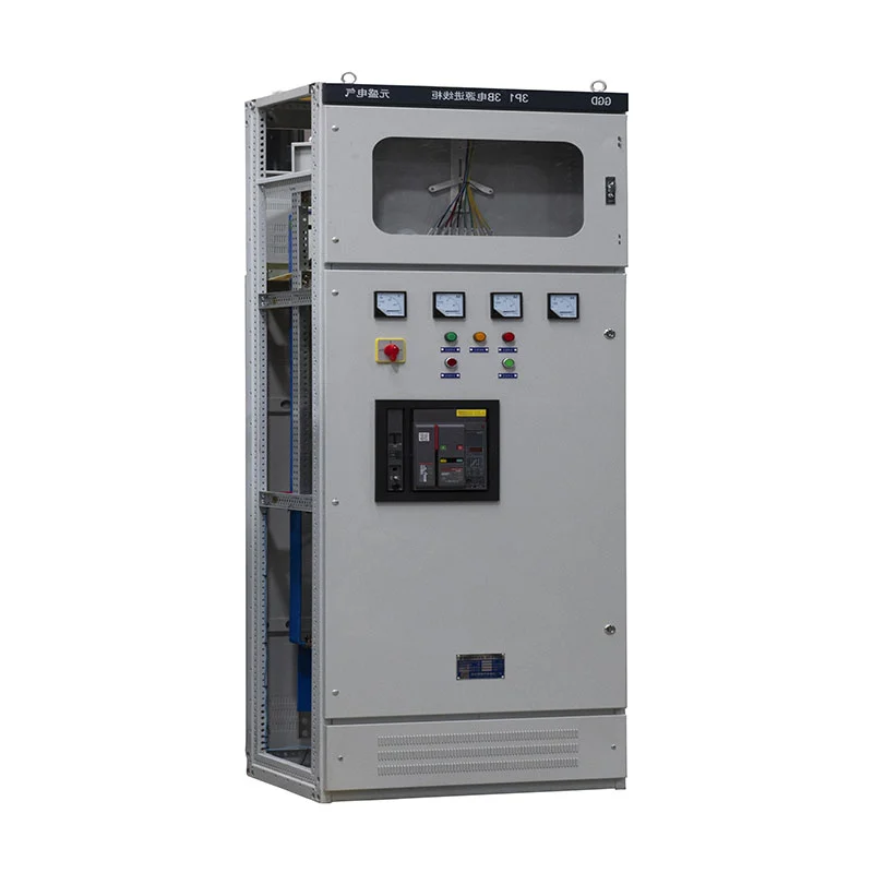
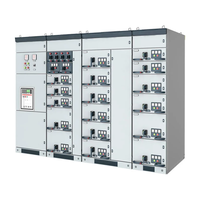
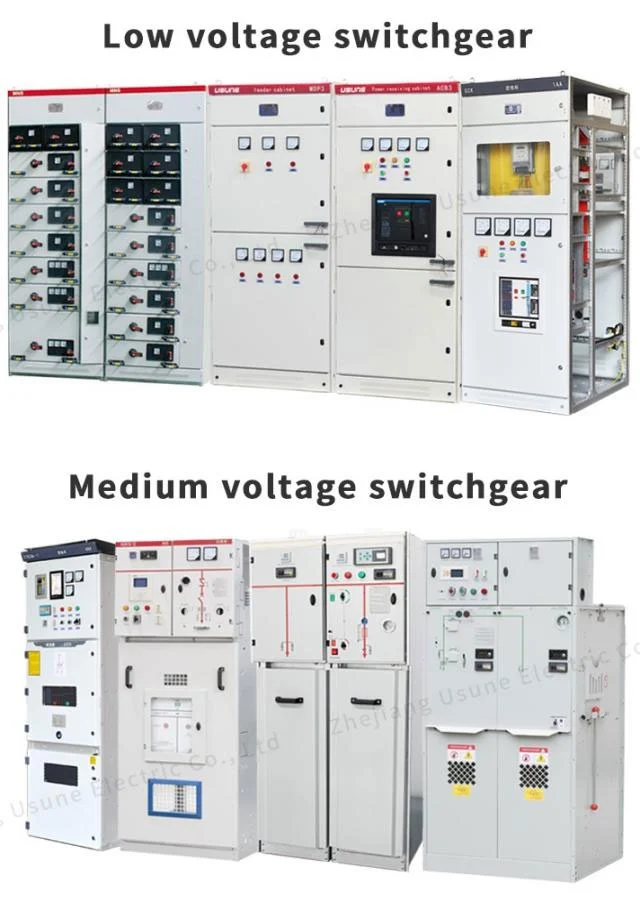
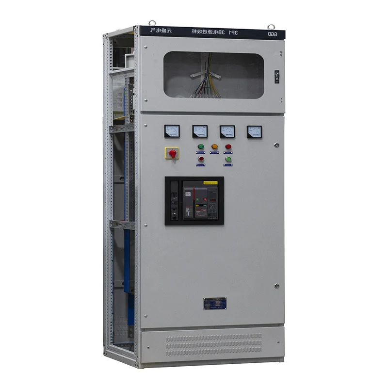
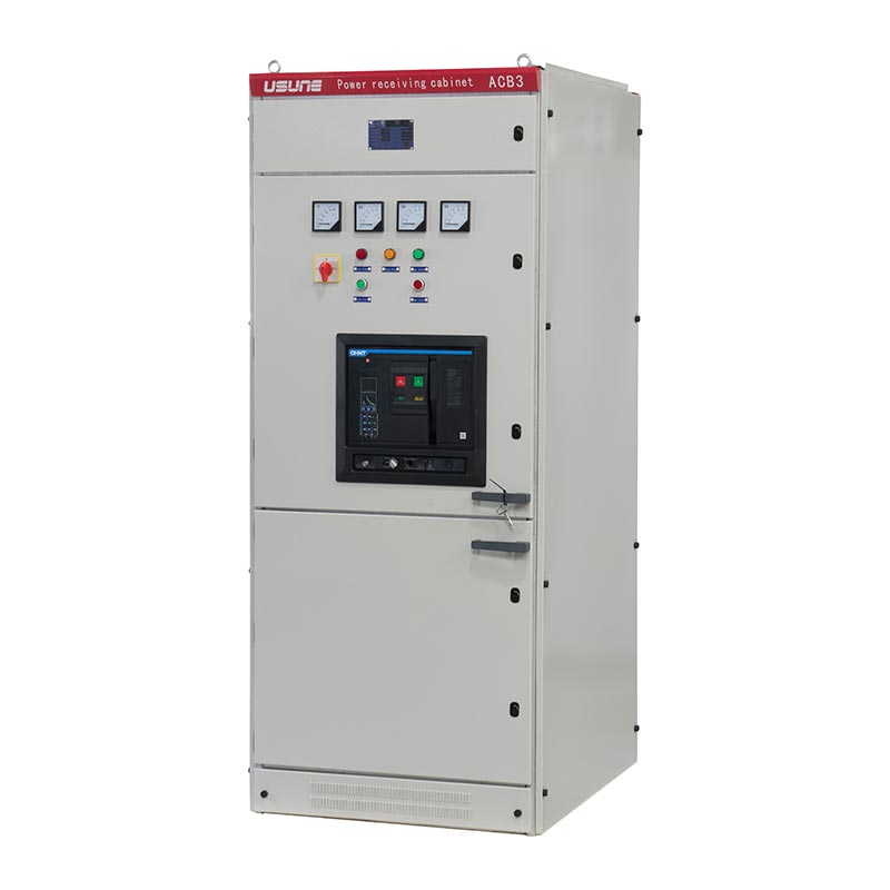
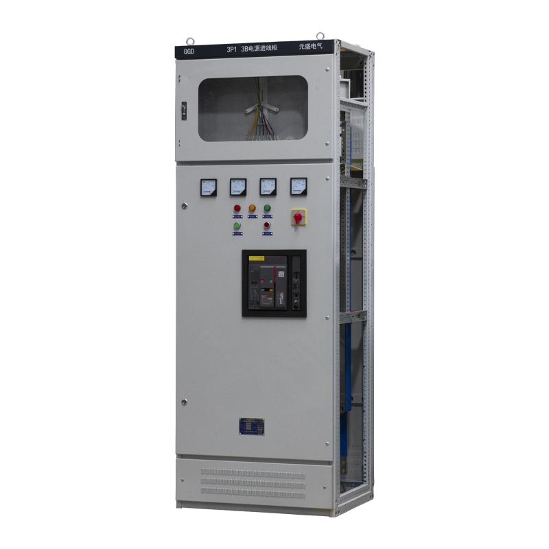
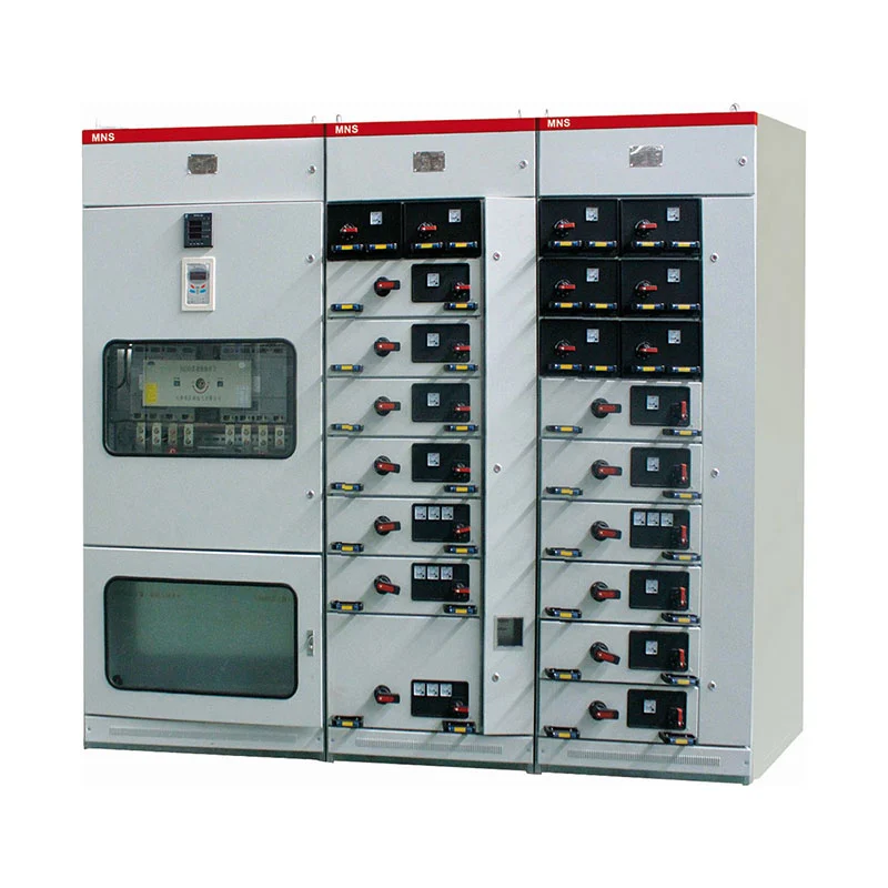
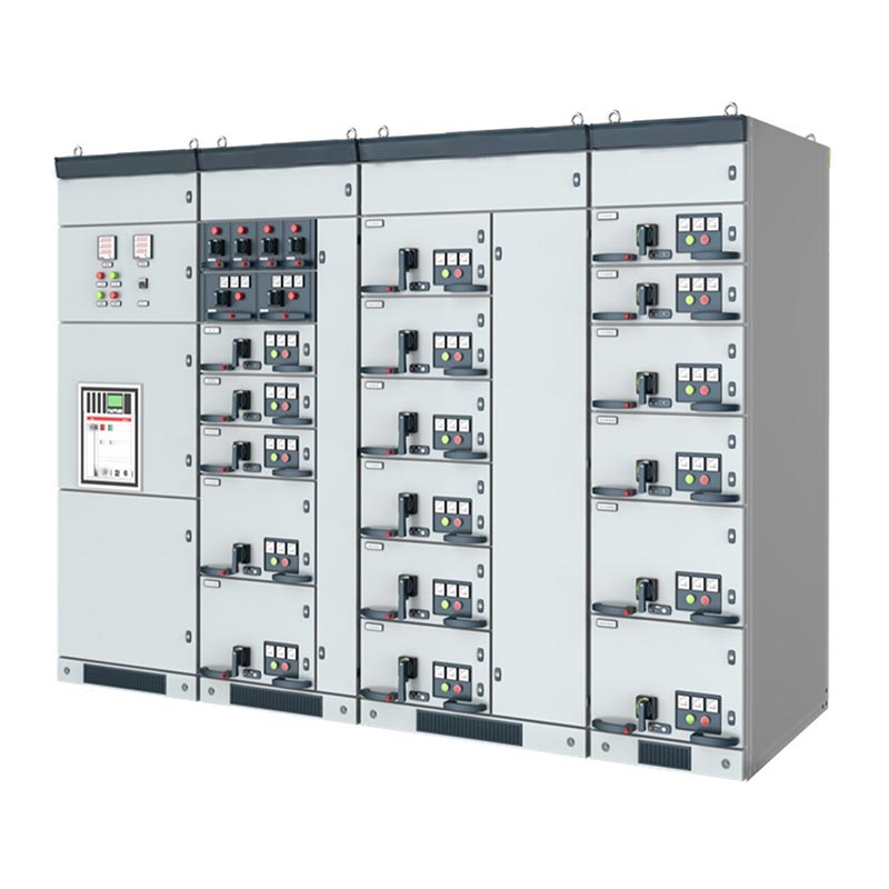
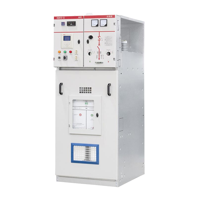
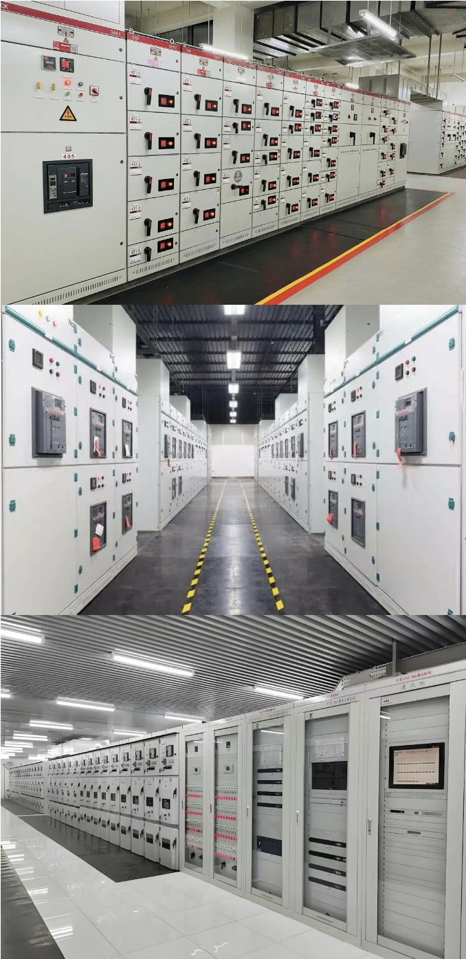
At Usune, we have developed our Low Voltage Withdrawable Distribution Switchboard to serve low-voltage power distribution networks that demand adaptable circuit setups, dependable power flow management, and well-defined control architectures. By leveraging a modular enclosure framework, our Low Voltage Switchgear can be tailored for tasks such as power reception, feeder dispatch, motor command, reactive power adjustment via capacitor banks, and additional distribution roles as dictated by specific engineering needs.
Rating: 5.0
(Rating Count: 1)

Overview

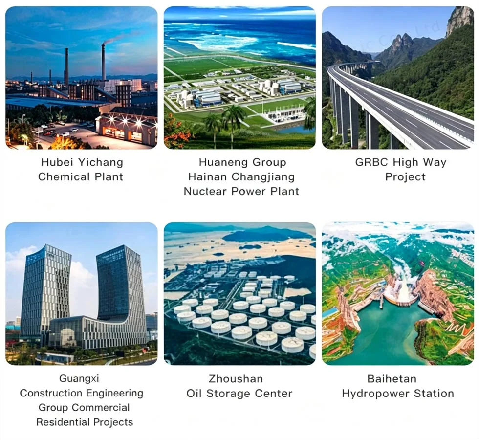
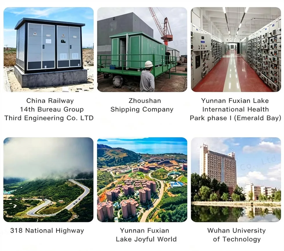
Developed by Zhejiang Usune Electric Co., Ltd., our Low Voltage Withdrawable Distribution Switchboard serves AC 50Hz systems with rated working voltage up to 400V and rated current up to 3150A. Copper busbar distribution, configurable circuit breakers, organized secondary wiring, and dedicated cable spaces come together in a design that supports different project layouts. At Usune, we manufacture and supply Low Voltage Switchgear solutions for power plants, substations, factories, mining facilities, commercial buildings, and other power distribution projects across China and overseas markets.

Flexible Feeder Arrangement

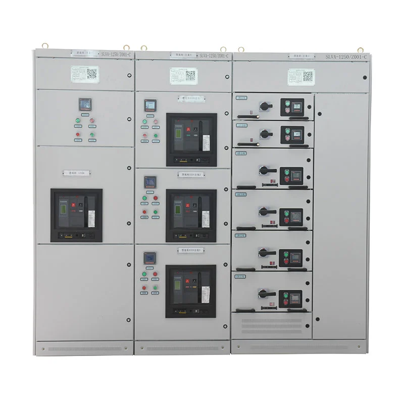
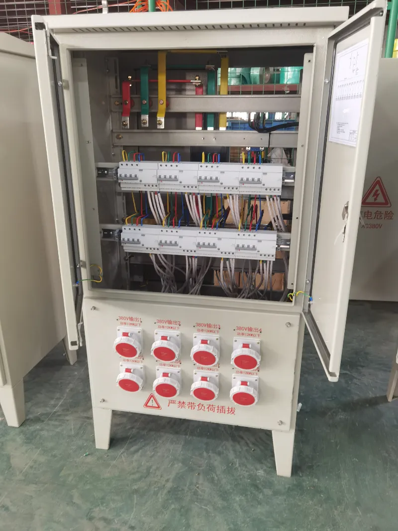
Because different electrical loads call for different feeder arrangements, the cabinet can be configured according to the power distribution diagram—allowing incoming circuits, outgoing circuits, motor feeders, and reactive power compensation circuits to be arranged within the same low-voltage distribution system.

Component Selection

Where larger distribution requirements apply, universal circuit breakers such as Emax, MT, 3WN, AH, and ME series can be chosen according to the project design. Molded case circuit breakers, load switches, and other electrical components may also be incorporated based on the required current rating and protection scheme.

Adaptable Configuration

Through this configuration approach, our Low Voltage Switchgear is able to adapt to different power distribution architectures rather than depending on one fixed electrical arrangement.

Low Voltage Withdrawable Distribution Switchboard


Busbar System

Electrolytic copper forms both the main and branch busbars, creating a stable current-carrying path between incoming and outgoing circuits. Flame-retardant insulation and heat-shrinkable sleeves are applied to relevant busbar sections, improving insulation protection while keeping phase identification clear.

Busbar arrangement follows the electrical drawing and rated current requirements. Where the project design calls for it, flexible busbar connections can be provided at the incoming connection between the bus bridge and the main circuit breaker.

For procurement teams, this configuration simplifies matching our Low Voltage Switchgear with upstream transformers, bus bridges, and downstream feeder systems.


Cabinet Construction

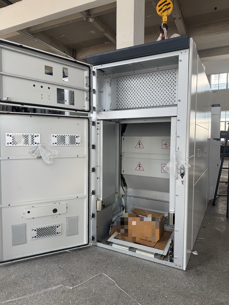
Cold-rolled steel plates are used for the cabinet frame and internal partitions, with a standard plate thickness of not less than 2 mm—providing sufficient mechanical strength for normal operation, inspection, and maintenance.

Dedicated areas within the cabinet structure accommodate electrical components, cable connections, and secondary control wiring. Doors, operating handles, identification plates, and internal labels are arranged according to the electrical design, making circuit identification easier during commissioning and maintenance.

A PE copper grounding bus runs along the cabinet arrangement direction. Components requiring grounding can be connected to this conductor, and dedicated grounding terminals are provided for connection to the external grounding network.


Secondary Control

The secondary circuit is arranged according to project drawings and control requirements. Control wiring uses flexible insulated copper conductors organized in bundles, giving the internal wiring a clean and maintainable arrangement.

Control circuits generally use 1.5 mm² conductors, while AC current circuits use 2.5 mm² conductors, subject to the final engineering design. Flame-retardant terminal blocks are used, and wire numbers or circuit identification marks correspond with the electrical drawings.

For incoming cabinets, undervoltage trip protection can be incorporated into the circuit breaker protection arrangement. Indicator lights, control switches, and measuring instruments can also be configured according to each circuit's function.


Distribution Functions

Our Low Voltage Switchgear can be configured for several common low-voltage power distribution functions. An incoming cabinet receives power from the upstream transformer or power source, while outgoing cabinets distribute electricity to downstream loads.

Motor control circuits can be arranged using large and small drawer configurations, with circuit breakers or fused rotary load switches selected according to motor characteristics. Capacitor compensation cabinets can incorporate manual, automatic, or remote reactive power compensation equipment.

This modular arrangement allows the same cabinet platform to support different electrical distribution tasks within one project.


Technical Specifications

Item Specification
Product Type Low Voltage Withdrawable Distribution Switchboard
Rated Working Voltage 0.4kV
Rated Frequency 50Hz
Rated Current Up to 3150A
Protection Degree IP23
Installation Indoor
Altitude ≤2000m
Pollution Level Level 3
Ambient Temperature -10°C to +40°C
Daily Average Relative Humidity ≤95%
Monthly Average Relative Humidity ≤90%
Seismic Intensity ≤Magnitude 8
Main Busbar Material Electrolytic Copper
Cabinet Material Cold-Rolled Steel Plate
Standard Cabinet Color Electric Gray, RAL7032
Model Rated voltage (V) Rated current (A) Rated short-circuit breaking current (KA) Rated short-time withstand current(1s) (kA) Rated peak withstand current (kA)
GGD1 380 A 1000 15 15 30
B 600(630)
C 400
GGD2 380 A 1500(1600) 30 30 63
B 1000
C 600
GGD3 380 A 3150 50 50 105
B 2500
C 2000

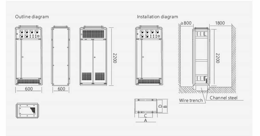
Product External Dimension

Low Voltage Withdrawable Distribution Switchboard

Product code A B C D
GGD06 600 600 450 556
GGD06A 600 800 450 756
GGD08 800 600 650 556
GGD08A 800 800 650 756
GGD10A 1000 600 850 556
GGD10A 1000 800 850 756
GGD12 1200 800 1050 756

Environmental Parameters and Operating Limits

At Usune, we engineer our Low Voltage Switchgear for deployment in interior settings that are free from intense mechanical shocks, corrosive atmospheres, or excessive vibration. The operational thermal range spans from -10°C up to +40°C, ensuring the 24-hour mean stays at or below +35°C. Our equipment is generally suited for elevations not surpassing 2000 meters. Regarding atmospheric moisture, when the surrounding temperature peaks at +40°C, the relative humidity must remain under 50%; however, increased moisture levels are acceptable at cooler temperatures, provided they align with the relevant environmental stipulations. The mounting angle must stay within 5 degrees of the vertical axis. Should a project demand deployment in atypical conditions, our Usune engineering crew will collaborate with the client to finalize a suitable technical configuration.


Protective Design and Cabinet Construction

Electrical safety is woven into both the physical build of the enclosure and the circuit defense mechanisms. Depending on the chosen arrangement, we integrate mechanical and electrical interlocks to minimize the risk of human error during operation. Each unit features unambiguous labeling for circuits and components. For fault protection, a standalone PE copper busbar is incorporated into the earthing layout. Furthermore, the cable chambers offer ample room for terminating cables and, where necessary, for installing zero-sequence current transformers. Access points, including front and rear panels, are crafted for smooth and secure movement, with control elements strategically placed to prevent any clash with doors or handles.


Standards, Certifications, and Documentation

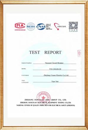
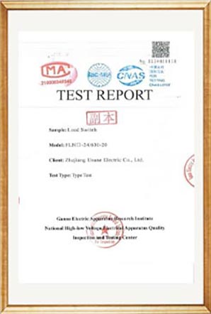
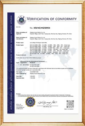
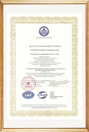
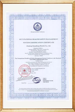
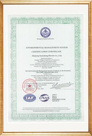
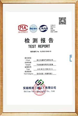
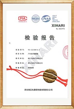
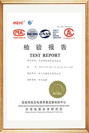
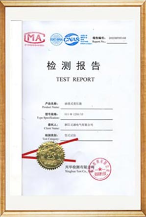
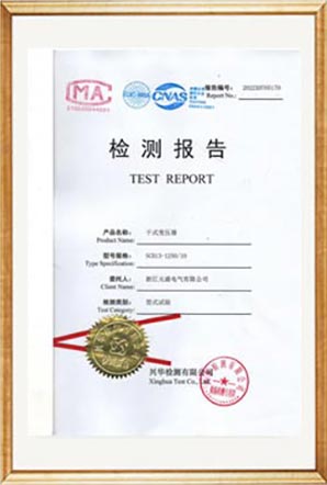
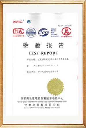
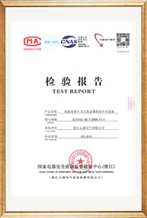
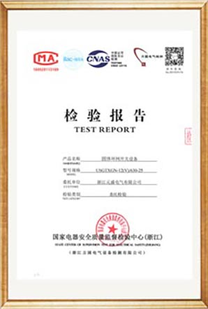
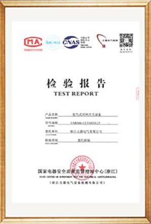
Our Usune manufacturing processes for low-voltage assemblies strictly follow pertinent IEC and GB directives, referencing benchmarks such as GB/T 14048.2, GB 7251.12, and associated international requirements. We uphold our production and management systems through ISO 9001, ISO 14001, and ISO 45001 accreditations. Upon request, we can furnish CE certification alongside relevant test records to satisfy specific project demands. These credentials equip procurement specialists with verifiable evidence for vendor assessment, project sign-off, and cross-border sourcing activities.


Test ReportTest ReportTest ReportTest ReportTest ReportTest ReportTest ReportTest ReportTest ReportTest ReportTest ReportTest ReportTest ReportTest ReportTest Report

Manufacturing Oversight and Quality Assurance

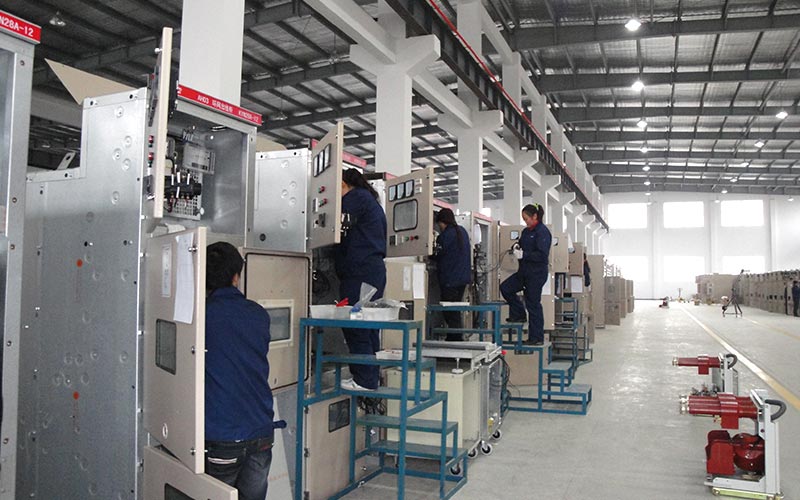
At Usune, our quality management system governs every phase of production, from enclosure materials and copper busbars to electrical components, secondary wiring, and the final assembled switchboard. All parts are sourced and installed in strict adherence to the approved engineering drawings and technical specifications. Before any equipment leaves our facility, it undergoes comprehensive routine inspections and functional testing. We meticulously verify wiring accuracy, component identification, grounding continuity, structural integrity, and electrical operations against the project’s documentation. This proactive approach helps prevent installation and commissioning challenges at the customer’s site. Additionally, our Usune team maintains detailed production and inspection records to support quality verification and ensure complete project traceability.


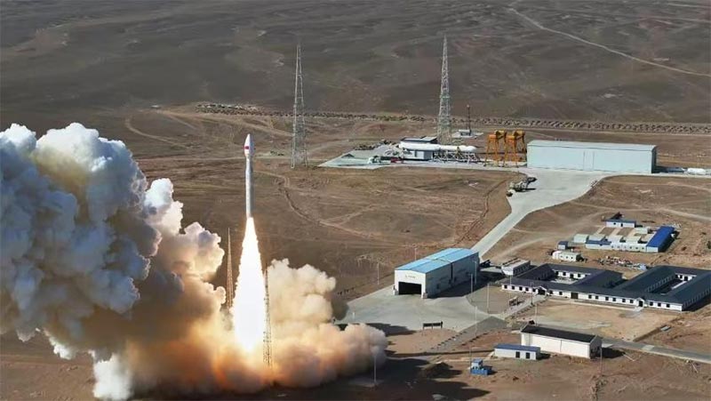
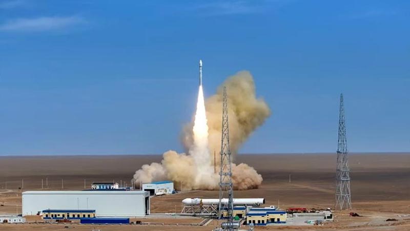
Application Case: Cas-space Rocket Launch Project

Our Usune Low Voltage Withdrawable Distribution Switchboard has been deployed at the Cas-space Rocket Launch Project, where highly reliable low-voltage power distribution is critical for both the facility’s infrastructure and its supporting electrical systems. For large-scale engineering projects featuring multiple electrical loads and diverse distribution circuits, our modular cabinet design allows for a tailored arrangement of incoming power, feeder lines, and auxiliary functions. This ensures the entire setup aligns perfectly with the project’s specific power distribution design.


Project ReferenceProject Reference

Cas-space Rocket Launch ProjectCas-space Rocket Launch Project

External Dimensions

The cabinet dimensions can be determined according to the approved electrical drawings, component selection, cable entry requirements and site installation conditions. Usune can provide corresponding dimensional drawings for engineering review before production.

Factory Testing

Usune performs inspection and routine testing before shipment. The testing process covers cabinet assembly, electrical connections, component installation, grounding, secondary wiring and other relevant functions.

Test reports and technical documentation can be provided according to the project requirements, helping customers complete incoming inspection, installation and commissioning procedures.

FAQ

What voltage is available?

The standard configuration is rated at 0.4kV, with a rated current of up to 3150A. The final electrical configuration is determined according to the project load and design drawings.

Can the cabinet be customized?

Yes. Usune can customize the cabinet configuration according to electrical schematics, circuit quantity, component selection, cable entry direction, cabinet dimensions and other project requirements.

What circuit breakers can be used?

The system can accommodate different circuit breaker configurations. Universal circuit breakers such as Emax, MT, 3WN, AH and ME series can be selected according to the approved design.

Can it be used for motor control?

Yes. Motor control configurations can be arranged using different drawer sizes and suitable circuit breakers or fused load switches according to motor capacity and protection requirements.

What busbar material is used?

The main and branch busbars use electrolytic copper. Relevant busbar sections can be provided with flame-retardant insulation and heat-shrinkable protective sleeves.

What documents can be provided?

Usune can provide technical specifications, electrical drawings, dimensional drawings, test reports and relevant quality documentation according to the project requirements.

What is the production lead time?

The standard lead time is generally 15–20 days, depending on configuration, quantity and project requirements.


Send Inquiry
Contact Info
If you have any inquiry about a quotation or cooperation, please feel free to email or use the following inquiry form. Our sales representative will contact you within 24 hours.
Rating:
5.0
X
We use cookies to offer you a better browsing experience, analyze site traffic and personalize content. By using this site, you agree to our use of cookies. Privacy Policy
RejectAccept