News

News

How Does an Outdoor Disconnect Switch Compare with a Circuit Breaker in Substation Applications?

2026-11-17 0 Leave me a message

In a high-voltage substation, an outdoor disconnect switch and a circuit breaker may appear to perform similar tasks because both are used to open and close electrical circuits. However, their engineering purposes are fundamentally different. A circuit breaker is designed to make, carry and interrupt current under specified operating conditions, including fault conditions. An outdoor disconnect switch is primarily used to establish an isolating distance and provide a visible separation point after the circuit has been safely de-energized. One device manages circuit interruption and protection, while the other supports electrical isolation and maintenance safety.


Understanding this distinction is essential when specifying equipment for transmission substations, distribution networks, transformer bays and industrial power systems. Zhejiang Usune Electric Co., Ltd. supplies GW4 and GW5 outdoor disconnect switch series for high-voltage applications, with voltage options across 12 kV, 24 kV, 35 kV, 72 kV, 110 kV, 126 kV, 145 kV and 170 kV, depending on the selected configuration. This article examines how the two devices differ in operation, protection, substation installation and technical selection, and explains why they are generally designed to work together rather than replace one another.

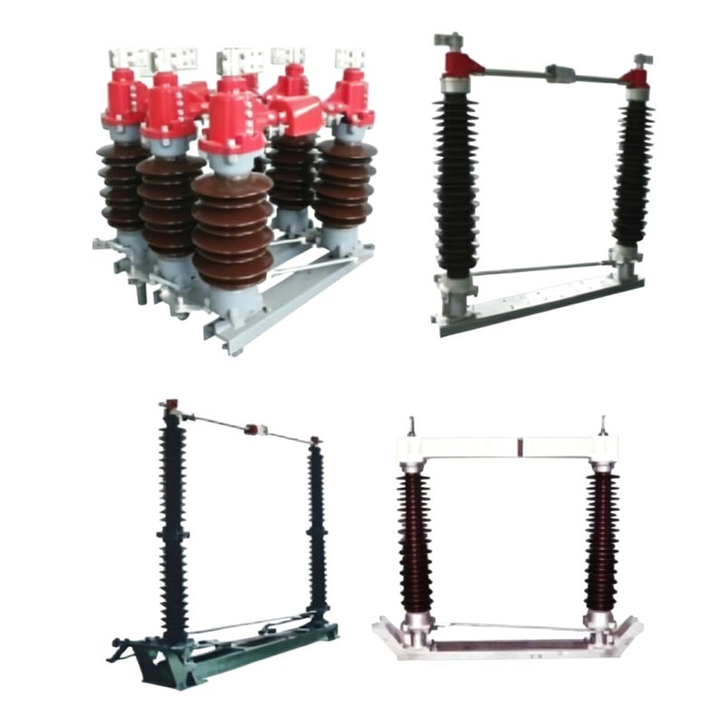
110kV 1250A 2000A Disconnector Switch


Table of Contents

1. What Are the Fundamental Differences in Operating Principles and Electrical Duties?

2. Why Do Substations Need Both Devices in Their Switching and Maintenance Procedures?

3. How Should Engineers Select an Outdoor Disconnect Switch for Substation Projects?

4. Conclusion

5. Frequently Asked Questions


What Are the Fundamental Differences in Operating Principles and Electrical Duties?

The distinction between a disconnect switch and a circuit breaker begins with the electrical conditions under which each device is expected to operate. Although both belong to the high-voltage switchgear system, they are not designed to perform the same switching duty. Engineers must understand the difference before preparing a single-line diagram, defining an equipment schedule or specifying a substation bay.

How Does a Circuit Breaker Interrupt Electrical Current?

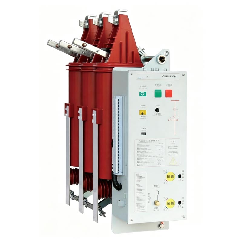
A circuit breaker is an active switching and protection device. Its main responsibility is to interrupt current when a switching command or protection signal requires the circuit to open. Under normal operating conditions, it can connect or disconnect an electrical circuit within its rated capabilities. When a fault occurs, protective relays detect abnormal electrical conditions and send a trip command to the breaker operating mechanism.

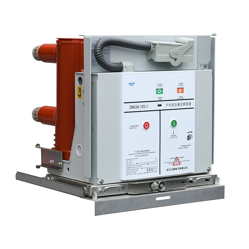
The interruption process is more demanding than simply separating two metal contacts. When contacts carrying current begin to move apart, an electrical arc can form between them. A high-voltage circuit breaker therefore incorporates an arc-extinguishing system designed to control and extinguish this arc under specified conditions. Depending on the equipment design, the interrupting medium may be vacuum, SF6 gas or another approved technology.

In a substation, circuit breakers are commonly installed in transformer bays, incoming and outgoing feeder bays, bus couplers and other positions where controlled interruption is required. Their performance is evaluated against several important electrical ratings:

  • Rated voltage, which defines the maximum system voltage class for which the equipment is designed.
  • Rated continuous current, which indicates the current the breaker can carry continuously under specified conditions.
  • Rated short-circuit breaking current, which defines its ability to interrupt a specified fault current.
  • Rated short-time withstand current, which describes its ability to carry fault current for a specified duration without unacceptable damage.
  • Rated peak withstand and making current, which relate to the mechanical and electrical stresses associated with high current peaks.
  • Operating sequence, which defines the required opening and closing operations under specified test conditions.

These ratings are not interchangeable. For example, a breaker with a high continuous current rating does not automatically have an adequate short-circuit breaking capacity. The fault level of the network, system voltage, transient recovery voltage and protection coordination must all be considered during equipment selection.

What Is the Main Purpose of a Disconnect Switch?

A disconnect switch, also called a disconnector or isolator, has a different operating role. It establishes an isolating distance between electrical conductors when the device is in its open position. In many outdoor high-voltage designs, the contact arrangement creates a visible air gap that can be checked by authorized operating personnel.

Unlike a circuit breaker, a conventional disconnect switch does not contain an arc-extinguishing system designed to interrupt normal load current or short-circuit current. It is therefore not intended to replace the circuit breaker when a feeder needs to be disconnected under load or when a protection relay detects a fault.

Under the IEC 62271-102 framework, a disconnector is a mechanical switching device that provides an isolating distance in the open position. It can carry normal operating current and withstand specified abnormal current conditions for a defined period, but its switching duty is restricted to the conditions permitted by its design and rating. This distinction is important because the ability to withstand short-circuit current does not mean that the device can interrupt that current.

The practical duties of a disconnect switch include:

  • Establishing an isolation point for transformers, busbars, circuit breakers and overhead line sections.
  • Providing a visible or reliably indicated open position for maintenance planning.
  • Separating equipment from energized sections after the appropriate switching sequence has been completed.
  • Supporting the application of an earthing switch where the selected configuration includes one.
  • Allowing authorized personnel to identify the intended isolation boundary before maintenance begins.

Our engineering approach treats isolation as a distinct safety function rather than an alternative form of circuit protection. This is why the rated operating duty, contact arrangement, insulation coordination and operating mechanism must be considered separately from the breaking capacity of a circuit breaker.

How Do Their Electrical Duties Compare in a Substation?

The following comparison summarizes the differences that matter most during substation design and operation.

Comparison Item Outdoor Disconnect Switch Circuit Breaker
Primary function Electrical isolation and establishment of an isolating distance Switching, current interruption and circuit protection
Load current interruption Not intended for ordinary load current interruption unless a specifically rated switching duty is provided Designed to interrupt current within its rated switching capabilities
Fault current interruption Cannot replace a circuit breaker for short-circuit interruption Designed to interrupt specified short-circuit currents
Arc-extinguishing system Conventional isolator design has no arc-extinguishing device Includes an arc-interruption system
Open-position indication Provides a visible or reliably indicated isolation gap Indicates the breaker contact position but does not automatically establish a maintenance isolation boundary
Typical operating role Isolation after the circuit has been interrupted Normal switching and fault clearing
Protection relay coordination Does not independently perform feeder fault protection Operates with protection and control systems to clear faults
Maintenance contribution Provides a defined isolation point for equipment maintenance Interrupts current before the isolation procedure proceeds

Why Is Withstand Current Not the Same as Breaking Current?

This is one of the most important technical distinctions for procurement teams. A disconnect switch may have a rated short-time withstand current and a rated peak withstand current. These ratings demonstrate its ability to remain electrically and mechanically stable while a specified fault current passes through the closed device for the defined test duration.

They do not indicate that the disconnect switch can open the circuit while that fault current is flowing. Current interruption requires the equipment to control the arc and withstand the recovery voltage that appears across the contacts after interruption. That duty belongs to a properly rated circuit breaker or another switching device specifically designed for the relevant load-breaking or fault-breaking duty.

For this reason, a technical comparison should never place a disconnect switch's short-time withstand current beside a circuit breaker's short-circuit breaking current as if they represented the same performance characteristic. They describe different electrical duties and must be assessed using the appropriate test requirements.

Our technical selection process therefore separates isolation requirements from interruption requirements. The project specification should identify the required voltage class, continuous current, short-time withstand level, peak withstand level and operating duty for each device. The circuit breaker's short-circuit breaking capacity must be checked against the calculated fault level at its installation point.

For standards-based engineering, IEC 62271-102 addresses alternating-current disconnectors and earthing switches, while IEC 62271-100 addresses high-voltage alternating-current circuit breakers. These standards cover different equipment categories and their respective performance requirements. Applying the correct standard to each device is essential for meaningful technical evaluation.


Why Do Substations Need Both Devices in Their Switching and Maintenance Procedures?

A substation is not designed around one switching device performing every electrical duty. It is an interconnected system in which circuit interruption, isolation, earthing, measurement, protection and control must work together. A circuit breaker and a disconnect switch serve different stages of this operating process. Their coordination is therefore a matter of system safety and equipment function, not simply a preference for installing more switching equipment.

How Do the Devices Work Together During Equipment Maintenance?

Consider a transformer bay that requires planned maintenance. The transformer cannot be treated as safely isolated merely because its circuit breaker has been opened. A complete switching programme must identify every possible source of supply, including busbar connections, alternative feeds, auxiliary supplies and any arrangement that could energize the equipment from another direction.

A typical isolation sequence may involve the following stages, subject to the approved switching procedure, substation design and local safety rules:

  1. Confirm the work boundary. The operating team identifies the equipment to be maintained, its connected circuits and every possible source of electrical energy.
  2. Interrupt the current. The circuit breaker is opened using the approved control procedure. If the operation is associated with a fault, the protection system may initiate the trip automatically.
  3. Establish the isolation point. The relevant disconnect switches are operated only after the circuit conditions permit their operation. Their open positions provide the required isolation distance.
  4. Verify the equipment condition. Position indications, interlocking arrangements and approved verification procedures are checked. A visual gap alone does not replace the full safety verification process.
  5. Apply earthing where required. After the absence of voltage has been established using approved methods, the designated earthing switch or portable earthing equipment is applied in accordance with the operating procedure.
  6. Complete the work authorization. Lockout, tagging, permits, communication and other site-specific safety controls are completed before maintenance starts.

The exact order and interlocking logic depend on the substation's single-line diagram and operating rules. In some installations, busbar arrangements or equipment configurations require additional switching steps. The important principle is that a disconnect switch is not operated as a substitute for a breaker when interrupting load current.

What Happens When a Substation Experiences an Electrical Fault?

During a short circuit, the system may experience a rapid increase in current, voltage disturbance and substantial electromagnetic forces. The protection system identifies the fault using the relevant current and voltage measurements, then issues a trip command to the circuit breaker responsible for isolating the affected circuit.

The circuit breaker must be capable of interrupting the prospective fault current at its installation point. Its interrupting rating, operating time and transient recovery voltage capability must be suitable for the network conditions. If the fault is not cleared correctly, the consequences can extend beyond the original equipment, potentially affecting busbars, transformers, cables and connected feeders.

A conventional disconnect switch does not perform this fault-clearing task. Its contacts and mechanical structure are designed around isolation and specified current-carrying duties, not the interruption of a high-energy fault arc. Attempting to use it to break a fault current can create severe arcing, equipment damage and serious personnel hazards.

Once the circuit breaker has cleared the fault and the circuit has reached the conditions required by the approved switching procedure, disconnect switches can be used to establish the necessary isolation points for inspection and repair. The two devices therefore contribute to different parts of the fault response and restoration process.

How Does Equipment Coordination Improve Substation Reliability?

Reliable substation operation depends on more than the individual performance of a circuit breaker or isolator. The equipment must be coordinated with protection relays, current transformers, voltage transformers, busbar arrangements, control circuits and operating interlocks.

Several engineering considerations deserve attention when designing this arrangement:

  • Protection selectivity: The protection scheme should identify the faulted section and command the appropriate circuit breaker to operate, limiting unnecessary interruption to healthy circuits.
  • Switching interlocks: Electrical and mechanical interlocks can help prevent prohibited operating sequences, such as attempting to operate a disconnect switch under conditions outside its permitted duty.
  • Position indication: The open and closed positions of disconnectors should be indicated through suitable mechanical or electrical arrangements. The indication system must correspond reliably to the actual contact position.
  • Earthing coordination: Earthing switches must be coordinated with the isolation arrangement and the relevant operating procedure to reduce the risk of accidental energization.
  • Insulation coordination: Equipment insulation levels must be suitable for the system voltage, switching conditions, lightning exposure and installation environment.
  • Maintenance access: Equipment layout should allow operators and maintenance teams to inspect contacts, insulators, mechanisms and operating linkages safely.

In an outdoor switchyard, the physical arrangement also matters. Adequate phase-to-phase and phase-to-earth clearances, equipment foundations, conductor connections and operating access all affect the installation's long-term reliability. A technically suitable device can still create operational difficulties if its mounting arrangement or linkage geometry does not match the substation design.

Which Project Conditions Make Outdoor Isolation Equipment Especially Important?

Outdoor substations are exposed to environmental conditions that can influence insulation performance, corrosion, mechanical movement and maintenance frequency. Rain, snow, wind, dust, salt contamination and temperature changes all need to be considered when specifying disconnectors and their supporting structures.

For example, a coastal substation may require particular attention to corrosion resistance and surface contamination. A high-altitude installation may require an engineering review of insulation performance and environmental correction factors. A site exposed to strong winds may need careful assessment of mechanical loads on the operating structure and connected conductors.

Our product range is intended for outdoor power transmission and distribution applications, including substations, utility networks and industrial power systems. The GW4 and GW5 series use weather-resistant open or semi-enclosed structures and are specified for an operating temperature range of -40°C to +45°C. The suitability of a particular configuration must still be checked against the actual site conditions and project specification.

A useful real-world reference is the Wuyuan 110 kV substation renovation project in Inner Mongolia. In May 2025, Zhejiang Usune Electric Co., Ltd. supplied 12 sets of GW5 series 110 kV outdoor disconnect switches for the project. The site was located in a plateau environment characterized by low temperatures and strong winds. The equipment was installed and commissioned over six days as part of the renovation work.

This project illustrates why the equipment's environmental suitability and installation coordination matter alongside its electrical ratings. It does not mean that every site with similar weather conditions can use the same configuration without engineering review. Foundation details, conductor connections, insulation requirements, operating mechanism selection and site acceptance criteria must all be checked for the individual project.


How Should Engineers Select an Outdoor Disconnect Switch for Substation Projects?

Selecting a disconnect switch for a substation requires more than matching the equipment's rated voltage to the nominal system voltage. The device must fit the electrical duty, mechanical arrangement, environmental conditions and operating philosophy of the installation. For engineers, EPC contractors, utility procurement departments and electrical equipment distributors, a complete technical review reduces the risk of specification gaps and costly changes during installation.

Which Electrical Ratings Should Be Confirmed First?

The first step is to define the system conditions at the proposed installation point. A project may require equipment for a 12 kV distribution system, a 35 kV industrial substation or a higher-voltage transmission application. The equipment's rated voltage must be selected in accordance with the system's highest voltage and applicable insulation coordination requirements, not simply the nominal voltage printed on the network diagram.

The following parameters should be included in the technical enquiry and equipment data sheet:

  • Rated voltage: Confirm the applicable equipment voltage class and system highest voltage.
  • Rated frequency: Verify whether the installation operates at 50 Hz or 60 Hz.
  • Rated continuous current: Confirm the required current-carrying capacity for the circuit under specified service conditions.
  • Rated short-time withstand current: Check the prospective short-circuit current and the required withstand duration.
  • Rated peak withstand current: Verify the peak electrodynamic stress that the equipment must withstand.
  • Power-frequency withstand voltage: Confirm the required insulation performance under the specified test conditions.
  • Lightning impulse withstand voltage: Check the insulation requirement associated with lightning overvoltage conditions.
  • Rated operating duty: Identify the required switching operations and whether special duties apply to the selected arrangement.

Rated current and short-time withstand current should not be confused. The former relates to continuous current carrying, while the latter relates to temporary fault-current withstand. Similarly, the peak withstand rating is not a breaking capacity. The circuit breaker installed in the same bay must be selected separately according to the system fault level and required interruption performance.

What Technical Information Is Available for the Usune GW4 and GW5 Series?

Zhejiang Usune Electric Co., Ltd. offers GW4 and GW5 outdoor high-voltage disconnect switch configurations for different power transmission and distribution requirements. The published series information identifies voltage options from 12 kV to 170 kV, with 50 Hz and 60 Hz AC system compatibility. These values describe the available series coverage and must not be interpreted as the rating range of one individual device.

Parameter Published Product Information Engineering Selection Note
Product series GW4 and GW5 Confirm the required design and model configuration
Rated voltage options 12 kV, 24 kV, 35 kV, 72 kV, 110 kV, 126 kV, 145 kV and 170 kV Series coverage only; confirm the exact model rating
Rated frequency 50 Hz and 60 Hz AC Match the local power system frequency
Installation type Outdoor high-voltage equipment Review site layout, mounting and environmental conditions
Structural design Weather-resistant open or semi-enclosed structure Confirm the configuration against pollution and exposure conditions
Main structural materials Steel and aluminum alloy Confirm material details and corrosion protection for the project
Operating temperature -40°C to +45°C Verify site temperature extremes and any special service conditions
Operating mechanism Manual and electric mechanisms Select according to local or centralized operating requirements
Remote operation Customizable Confirm control voltage, interface and remote signalling requirements
Arc-extinguishing device Not provided in the conventional disconnect switch design Use a separately rated circuit breaker for load and fault interruption
Rated current Model-specific value to be confirmed Request the exact technical data sheet
Short-time and peak withstand current Model-specific values to be confirmed Match the substation fault study and required duration
Insulation levels Model-specific values to be confirmed Verify power-frequency and lightning impulse withstand ratings

The distinction between available series options and model-specific technical values is particularly important in high-voltage procurement. A project requiring a 110 kV installation should not assume that every item in the product family shares the same rated current, insulation level or short-time withstand performance. Those values must be documented for the selected model and confirmed against the approved project specification.

How Do the GW4 and GW5 Configurations Fit Different Substation Requirements?

GW4 and GW5 are established model designations used for outdoor high-voltage disconnectors. The correct selection depends on the required voltage class, installation arrangement, operating mechanism, insulation design and project interface. A model number alone is not enough to establish that a device is suitable for a particular bay.

The published Usune product information identifies a GW4 110 kV configuration with a double-column horizontal rotating, center-break arrangement for three-phase AC 50/60 Hz systems. This type of layout is relevant to substation designs where the equipment arrangement and the required open isolation distance must be coordinated with the busbar and conductor geometry.

For GW5 applications, the Wuyuan project provides a documented example of a 110 kV installation. Twelve sets were supplied for a substation renovation in a low-temperature, high-wind plateau environment. The installation and commissioning work was completed over six days. This project reference provides practical context for the use of the series in outdoor substation renovation work, but it should not be treated as a universal installation duration or a substitute for project-specific technical verification.

Before selecting either configuration, our engineering team recommends reviewing the following project interfaces:

  • Single-line diagram and bay arrangement.
  • Busbar and conductor connection positions.
  • Phase spacing and required electrical clearances.
  • Support structure, foundation and mounting dimensions.
  • Operating shaft, linkage and mechanism installation space.
  • Grounding switch requirements, if included in the selected configuration.
  • Electrical and mechanical interlocking requirements.
  • Local control cabinet and remote operation interface.
  • Maintenance access and visible isolation requirements.

These details should be agreed before manufacturing because a mismatch in mounting dimensions or operating linkage can create unnecessary site modifications. The project team should also confirm whether the equipment requires a single grounding switch, double grounding arrangement or no integrated grounding switch, since this is a configuration issue rather than an automatic feature of every disconnector.

What Should Buyers Ask a Manufacturer Before Placing an Order?

A complete technical enquiry should contain enough information for the manufacturer to identify the intended operating conditions and propose a suitable configuration. General product descriptions are useful for initial research, but they are not a replacement for model-level drawings and technical schedules.

For procurement teams, the following checklist provides a practical starting point:

  1. What is the rated voltage and highest system voltage at the installation point?
  2. Does the site operate at 50 Hz or 60 Hz?
  3. What continuous current rating is required?
  4. What are the calculated short-time and peak fault-current levels?
  5. What insulation levels are required by the project specification?
  6. Is a manual or electric operating mechanism preferred?
  7. Does the substation require local operation, remote operation or both?
  8. Is an integrated earthing switch required, and what arrangement is specified?
  9. What are the installation dimensions, terminal requirements and foundation details?
  10. Which environmental conditions, including altitude, pollution, wind, temperature and corrosion exposure, must be considered?
  11. Which IEC, national or utility-specific standards and type-test documents are required?
  12. What inspection, acceptance, commissioning and documentation requirements apply?

For international projects, buyers should also clarify the destination country's grid requirements, documentation language, inspection procedures, packing conditions and delivery scope. If a project is part of a utility upgrade, the technical specification may contain additional requirements for interlocking, remote signalling, operation counters, auxiliary contacts or control circuit arrangements.

Our factory supports technical discussions around the intended voltage class, operating method, structural arrangement and environmental conditions. Zhejiang Usune Electric Co., Ltd. can review customer drawings and project requirements to clarify the proposed equipment configuration before order confirmation. The final technical agreement should identify all applicable ratings and interfaces so that the supplied equipment can be checked against the approved design.


Conclusion

An outdoor disconnect switch and a circuit breaker perform different but complementary duties in substation applications. The circuit breaker interrupts load and fault currents within its rated capability, while the disconnect switch establishes an isolation distance for maintenance and operational safety. Neither device should be selected as a direct substitute for the other. Proper coordination, accurate equipment ratings and a clearly defined switching procedure are essential to reliable substation operation. Zhejiang Usune Electric Co., Ltd. provides GW4 and GW5 outdoor disconnect switch solutions for different high-voltage applications. Contact our team with your system voltage, current requirements, fault-level data and installation conditions to request model-specific technical information and discuss a suitable configuration for your substation project.


Frequently Asked Questions

Can an outdoor disconnect switch interrupt load current in a substation?

A conventional outdoor disconnect switch is not designed to interrupt normal load current or short-circuit current because it does not have the arc-extinguishing system required for those duties. It is normally operated after the circuit breaker has interrupted the current and the circuit conditions permit isolation. Some specialized switching devices have additional rated switching duties, but these must be explicitly stated in the manufacturer's technical documentation. A standard disconnector should never be treated as a substitute for a circuit breaker.


Why is a visible isolation gap important when maintaining substation equipment?

A visible isolation gap provides a direct indication that the relevant disconnecting contacts have reached the open position and that an isolating distance has been established. This helps operating personnel identify the intended separation point during maintenance planning and switching procedures. However, a visible gap alone does not prove that equipment is safe to touch. Approved voltage verification, earthing, lockout and tagging, interlocking and work authorization procedures remain necessary under the applicable site safety rules.


Can a disconnect switch withstand short-circuit current without being able to break it?

Yes. A disconnect switch may be designed to carry a specified short-circuit current for a limited duration while remaining in the closed position. Its rated short-time withstand current and peak withstand current describe its ability to withstand thermal and electrodynamic stresses during that period. They do not represent a short-circuit breaking rating. Interrupting fault current requires a circuit breaker or another device specifically designed and rated for that switching duty.


What is the difference between IEC 62271-100 and IEC 62271-102?

IEC 62271-100 covers high-voltage alternating-current circuit breakers, including their applicable ratings and making and breaking performance requirements. IEC 62271-102 covers alternating-current disconnectors and earthing switches, focusing on their isolation and earthing functions. The two standards address different equipment categories, so a substation specification should identify the appropriate standard for each device. Buyers should also confirm the applicable edition, national adoption and project-specific requirements with the responsible engineering authority.


What information is needed to select a GW4 or GW5 outdoor disconnect switch?

Selection requires the system voltage, frequency, rated continuous current, short-time and peak withstand current, insulation levels, installation arrangement and environmental conditions. The project team should also define the operating mechanism, remote control requirements, grounding switch configuration, interlocking interfaces, mounting dimensions and applicable standards. The Usune GW4 and GW5 series cover several voltage options, but the ratings of an individual model must be confirmed through its technical datasheet and approved drawings before procurement.

Related News
Leave me a message
X
We use cookies to offer you a better browsing experience, analyze site traffic and personalize content. By using this site, you agree to our use of cookies. Privacy Policy
RejectAccept