Products

Products

630a Sf6 Ring Main Unit
  • 630a Sf6 Ring Main Unit630a Sf6 Ring Main Unit
  • 630a Sf6 Ring Main Unit630a Sf6 Ring Main Unit
  • 630a Sf6 Ring Main Unit630a Sf6 Ring Main Unit

630a Sf6 Ring Main Unit

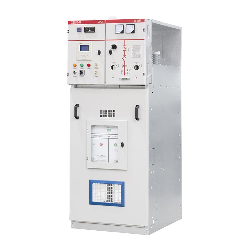
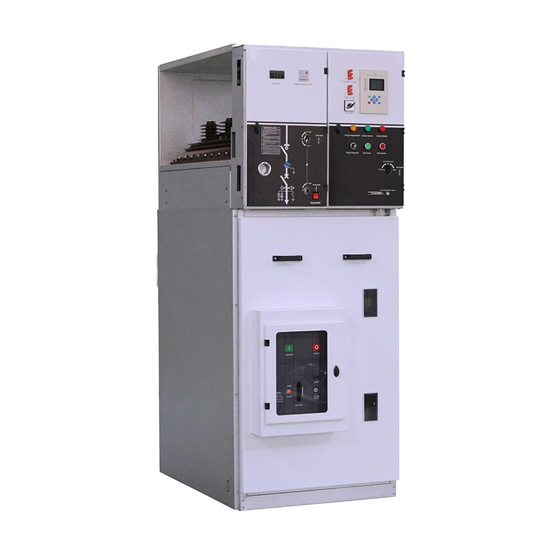
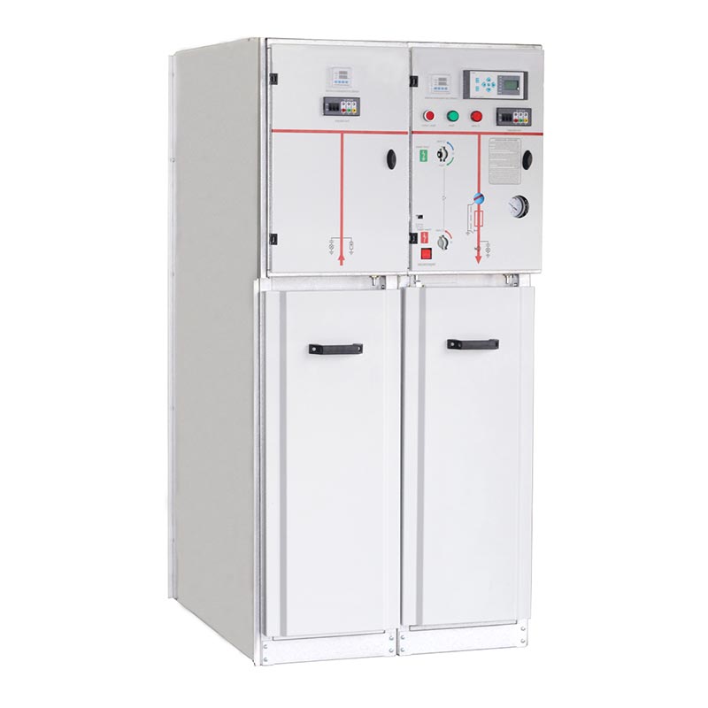
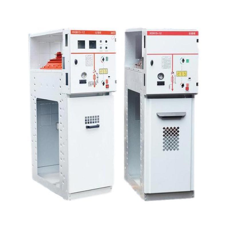
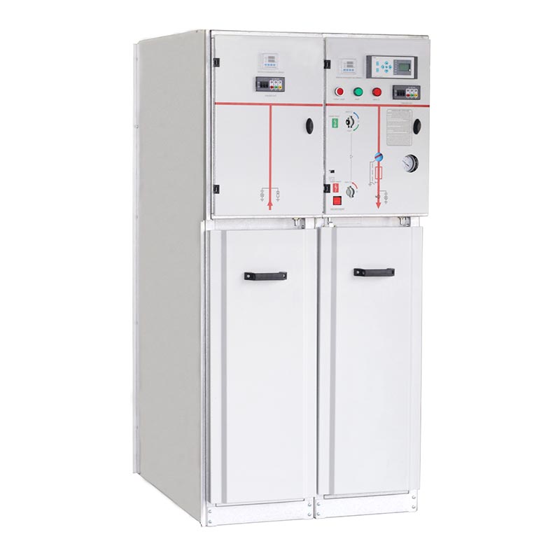
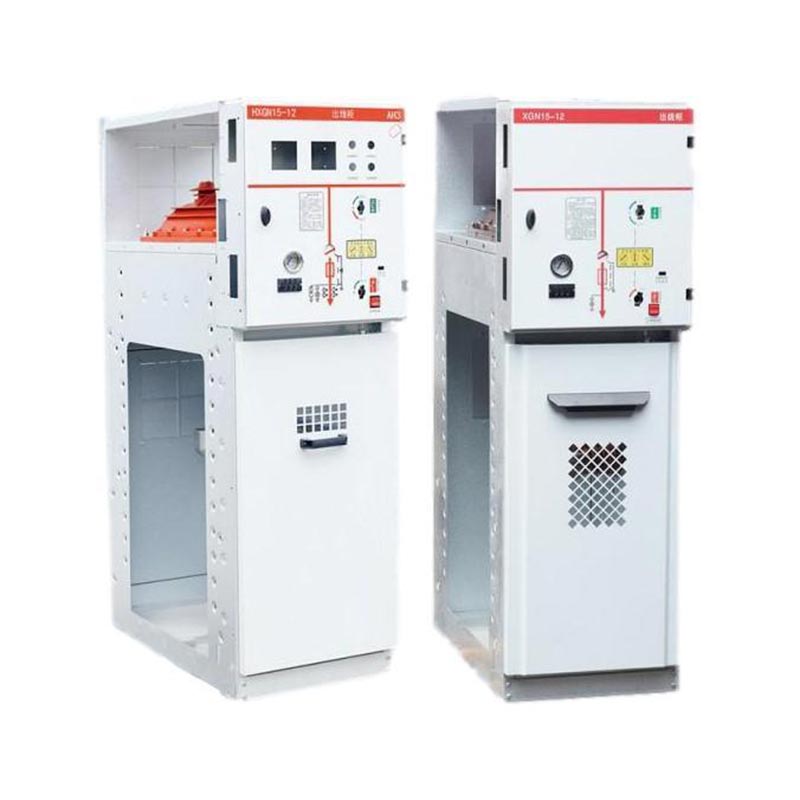
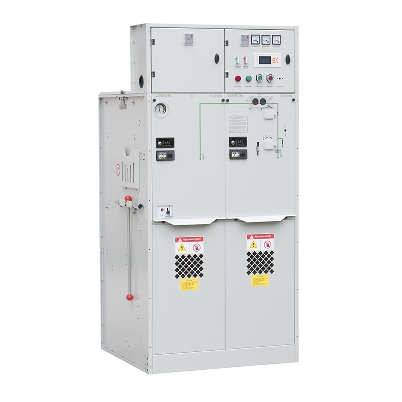
As a professional manufacturer with many years of experience in the R&D and production of electrical equipment, USUNE has launched the HXGN15-12 box-type fixed metal-enclosed 630a Sf6 Ring Main Unit (SF6 RMU), specifically designed for AC 50/60Hz power systems with rated voltages of 12kV, 24kV, and 36kV. Using SF6 gas as the core insulation and arc-quenching medium, the product features a compact structure, light weight, excellent insulation performance, and maintenance-free operation, making it widely applicable in various industrial and civil power supply scenarios. As a reliable supplier rooted in China, USUNE relies on standardized factories and a strict quality control system to ensure product stability and safety, providing high-quality power distribution solutions to users worldwide.

The USUNE 630a Sf6 Ring Main Unit is a high-performance medium-voltage power distribution equipment independently developed and manufactured by Zhejiang Yousi Electric Co., Ltd. (a professional manufacturer integrating R&D, production, and sales of electrical equipment). This product features a box-type fixed metal enclosed structure, using SF6 gas as insulation and arc-extinguishing medium. Equipped with SF6 gas-insulated switch fuses, it is primarily used in secondary distribution networks with a maximum rated voltage of 36kV and a rated current of 630A, perfectly adaptable to the power supply requirements of AC 50/60Hz power systems.

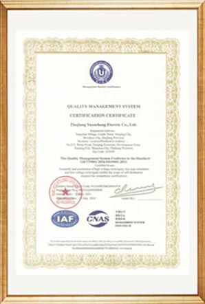
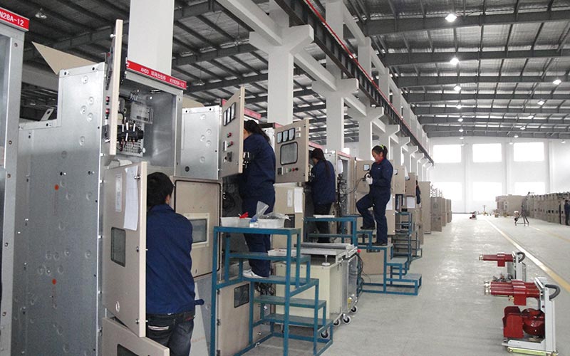
As a leading supplier in China's electrical equipment industry, USUNE adheres to a high-quality production philosophy. This 630A SF6 ring main unit is manufactured in the company's standardized factory, where strict quality control is implemented throughout the entire process from components to finished product, ensuring product reliability and consistency.

630a Sf6 Ring Main Unit630a Sf6 Ring Main Unit

Core Product Features

1. Compact and Lightweight Design

The 630a SF6 Ring Main Unit adopts a compact structure and lightweight design, effectively saving installation space and reducing transportation and installation costs. The epoxy resin shell provides a tight seal, making it suitable for space-constrained scenarios such as small machine rooms and prefabricated substations, enhancing on-site application flexibility.

2. Excellent Insulation and Arc-Suppressing Performance

The enclosed casing is filled with SF6 gas, providing excellent insulation and arc-suppressing performance. It is highly resistant to moisture and pollution, allowing for stable operation in harsh environments and near-maintenance-free operation, significantly reducing subsequent maintenance costs.

3. Simple Operation and Easy Installation

The 630a SF6 Ring Main Unit features a front-end cable connection design, with all control functions centralized on the front panel, simplifying the operation process and facilitating operation and debugging. Its lightweight and compact design makes installation more efficient, allowing for rapid deployment after installation.

4. Abundant Accessories

Various accessories such as relays, transformers, and surge arresters can be equipped to meet the different functional requirements of various power distribution scenarios, enhancing product adaptability and practicality.

Applicable Scenarios

The USUNE 630a SF6 Ring Main Unit is widely used in industrial and civil cable ring networks and power supply terminals. It is particularly suitable for small secondary substations, switching stations, urban residential power distribution, industrial and mining enterprises, shopping malls, airports, subways, wind power generation, hospitals, stadiums, railways, and other locations, providing reliable power supply for various scenarios.

Operating Conditions

To ensure stable and safe operation, this ring main unit has strict environmental requirements, as follows:

- Altitude: ≤1000mm
- Ambient Temperature: -35℃~45℃
- Relative Humidity: Daily average not exceeding 95%; monthly average not exceeding 90%
- Seismic Resistance: Seismic intensity not exceeding 8 degrees
- Environmental Requirements: Locations free from severe vibration, impact, fire, chemical corrosion, and explosion hazards.

Technical Parameters

S/N Name Unit Value
1 rated voltage kV 12 24 36
2 ratedcurrent A 630 630 630
3 rated closed loop breaking current A 630 630 630
4 rated on load breaking current A 630 630 630
5 rated short time withstand current kA 16 16 16
6 rated peak withstand current kA 40 40 40
7 rated short-circuit making current kA 40 40 40
8 rated power frequency withstand voltage Phase-to-phase and phase-to-earth kV 28 50 70
9 across the isolating distance kV 32 60 80
10 rated lightning withstand voltage Phase-to-phase and phase-to-earth kV 75 125 170
11 across the isolating distance kV 85 145 195
12 rated transfer current A 630 630 630
13 mechanical endurance ops M1 1000 M1 1000 M1 1000
14 electrical endurance ops E1 E1 E1
15 pressure of SF6 gas(20℃) bar 0.5 0.5 0.5
16 yearly leakage rate ≤% 0.5 0.5 0.5
17 enclosuredegree of protection IP3X IP3X IP3X

Switchgear structure and configuration

630a Sf6 Ring Main Unit

Operating mechanism

(1) Double-function single-spring operating mechanism: type K

The switching function is operated independently with a lever or motor.
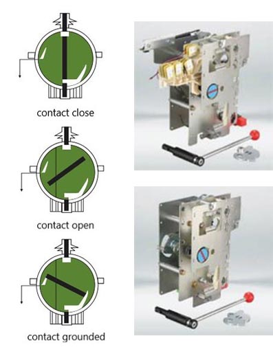
The ground switch function independently opens and closes using an operating lever, and the operating energy is provided by a compression spring, which is released to close or disconnect the contact.

(2) Double function double spring operating mechanism: Type A

The switching function is operated independently by a lever or motor, and the operating energy is provided by a compression spring, which is released to close the contact. Independent opening and closing operation with button (0) or tripping unit or shunt tripping device.
The ground switch function operates independently with an operating lever and the operating energy is provided by a compression spring, which is released to close or disconnect the contact.

(3) Optional components

One electric operation: AC 220V 110V; DC 220v 110v
Auxiliary switch
One shunt trip coil (Type A mechanism) : AC 220V 110V; DC 220v 110v
A fuse fuses auxiliary indicator switch
Earth fault indicator

630a Sf6 Ring Main Unit

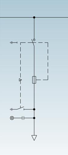
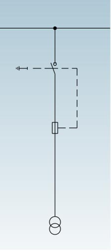
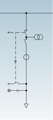
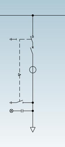
Switch and fuse protection cubicles

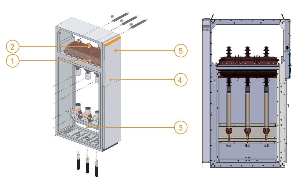
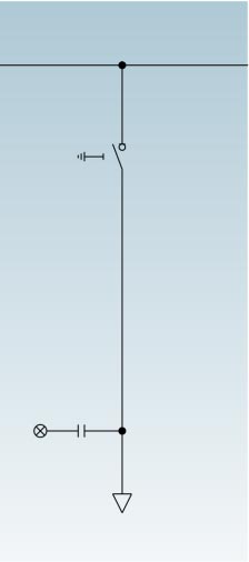
1 Switchgear Switch and earthing switch in an enclosure filled with SF6.
2 Busbars all in the same horizontal plane, thus enabling later switchboard extensions and connection to existing equipment.
3 Connection accessible through front, connection to the lower switch and earthing switch terminals or the lower fuse-holder. This compartment is also equipped with an earthing switch downstream from the MV fuses for the protection units.
4 Operating mechanism contains the elements used to operate the switch and earthing switch and actuate the corresponding indications (positive break).
5 Low voltage installation of a terminal block (if motor option installed), LV fuses and compact relay devices. If more space is required, panel height may be increased.

630a Sf6 Ring Main Unit

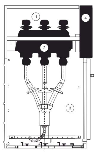
① Busbar room
② Main switch
③ Cable room
④ Operating mechanism, interlocking mechanism and low pressure control room

The whole switchgear cabinet can be divided into upper and lower two units, the upper unit of the cabinet includes the bus room, load switch, operating mechanism room and low voltage room, and the lower unit is separated from the cable room. The entire upper unit can be replaced.

◇ Busbar room

The busbar room is arranged on the upper part of the cabinet. In the busbar room, the main busbars are connected together and run through the whole row of switchgear.

◇ Load break switch

The switch room is equipped with an SFG type sulfur hexafluoride load switch. The shell of the load switch is made of epoxy resin poured, filled with sulfur hexafluoride (SF6) gas as the insulating medium, and the shell is provided with an observation hole. The switch room can be equipped

with SF6 gas density meter or gas density with alarm contact according to customer requirements.

◇ Cable room

The load switch cabinet has a spacious cable room, which is mainly used for cable connection, so that single-core or three-core cables can be connected using the simplest unshielded cable head, and sufficient space can also accommodate lightning arrester, current transformer, lower ground switch and other components. According to the standard design, the cabinet door has an observation window and a safety interlock device. Cable room bottom plate with seal cover and appropriate size cable clamp with support bracket. Cable room bottom plate and door frame can be removed to facilitate cable installation.

◇ Operating mechanism, interlocking mechanism and low pressure control room

The interlocked mechanism room also acts as a control panel. The low-voltage room is equipped with a spring-operated mechanism with a position indicator and a mechanical interlocking device, and can also be equipped with auxiliary contacts, trip coils, emergency trip mechanisms, capacitive live displays, key locks and electric operating devices. At the same time, the low-pressure chamber space can also be equipped with control loops, meters and protective relays, and the 750mm wide cabinet has two identical low-pressure chambers for more accessories.

Enclosure configuration parameter

No. Switchgear Type Optional Configuration Enclosure Dimensions(WxDxH)mm
Breaker Current instrumenttransformer Transformer Load switch Disconnector Earthing switch Fuse Main busbar Relay protection 12 24 36
1 Incoming/Outgoing LBS Panel 375×1000×1635.500×1000×1885etc. 375×1000×1635,500×1000×1885,600×1200×2000 etc. 750×1400×2250,900×1600×2300 etc.
2 Transformer Protection Panel 375×1000×1635.500×1000×1885 etc. 375×1000×1635,500×1000×1885,600×1200×2000 etc. 750×1400×2250,900×1600×2300 etc.
3 Metering Panel 500×1000×1635 etc. 750×1000×1635 etc. 750×1400×2250etc.
4 CB Outgoing Panel 500×1000×1635,750×1000×1635 etc. 750×1000×1885,800×1200×2200 etc. 1000×1400×2250etc.
5 CB Outgoing with Metering Panel 750×1000×1635 etc. 750×1000×1885 etc. 1000×1400×2250etc.
Incoming LBS

Incoming LBS

Trafo protect

Trafo protect

Metering

Metering

Cbog w/.meter

Cbog w/.meter

Cb outgoing

Cb outgoing

Operation description

1.Operation of handle:Standing in front of the switchgear, hold up the top of the handle and push forward, the other hand holding the end of the handle to rotate.
2.Make sure that the cabinet door has been properly closed before power supply or separate to grounding.
3.Switch pressure gauge must be checked before power on and power off.

Power on

1.Confirm that the cabinet door is closed.Insert the handle into the upper operating hole and anticlockwise rotate 180°until to hear voice of separating brake.The central indicator of the panel is in position; the lower door is closed and the grounding switch is off.
2.Insert the operating handle into the lower operating hole and clockwise rotate 180°until to hear the closing voice; the central indicator of the panel is in position D; the switch will be on, and then power supply operation is completed.

Power off

1.Switch off:Insert the operating handle into the lower operating hole and anticlockwise rotate 180°until to hear the separating brake voice(Direct use button if there is a button);the center of the panel is in position ,then the switch will be off.
2.Check whether the live display is out to ensuring the cable room is electrically neutral;insert the operating handle into the upper operating hole and clockwise rotate 180°until to hear the closing voice;the central indicator of the panel is in position and the lower door is unlocked;the grounding switch is closed and then power interruption operation is completed.

Transportation and storage

When the switch cabinet is fixed on the bottom plate, it can be shovel by forklift. When it is not fixed on the bottom plate, the switch cabinet should be hoisted or carried as a whole, but it should be transported vertically at any time and should not be overturned to avoid damage to the components in the cabinet. Switchgear (even with outer packaging) should not be stored outside for a long time.

Maintenance

◇ The ring cabinet is maintenance-free for three years under normal circumstances.

◇ The single-spring and double-spring operating mechanisms of the load switch are maintenance-free and do not require any lubrication.

◇ The relay protection device shall be checked according to the manufacturer's requirements before being put into operation.

◇ The maintenance cycle of the ring network cabinet is generally once a year, and specific maintenance measures shall be carried out as follows:
(1) Tighten all electrical connections (main bus, switches, cables, metering instruments) according to the requirements of the installation instructions.
(2) Vacuum all components (main switch, auxiliary switch, trip mechanism, motor, etc.) and conduct appearance inspection.
(3) Perform a single closing/opening operation on all switches, including the ground switch.
(4) Turn on the auxiliary control power supply (do not give the remote control signal) for an electrical sequential operation.

Order goods

The following documents and attachments will be handed over with the cabinet when the switch cabinet leaves the factory:

◇ Product qualified certificate
◇ Product use instructions
◇ Product engineering design data
◇ Switch cabinet accessories:
◇ Each mounting combination is equipped with a load switch operating handle.

Users should provide the following information when ordering products:

◇ Main circuit wiring scheme and special technical requirements
◇ Switchgear installation plan.
◇ Switch cabinet components model specifications and auxiliary loop, control loop schematic diagram (if necessary)
◇ Other special requests for written information.

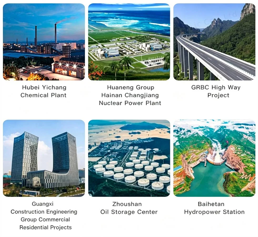
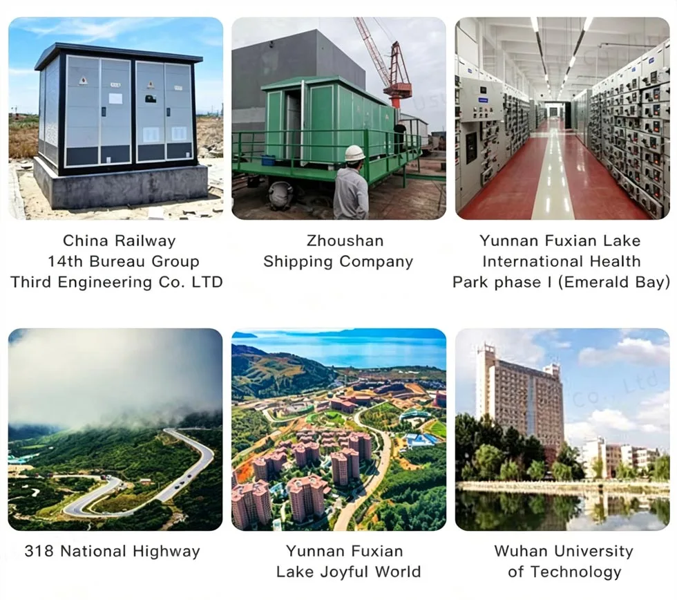
Project Reference

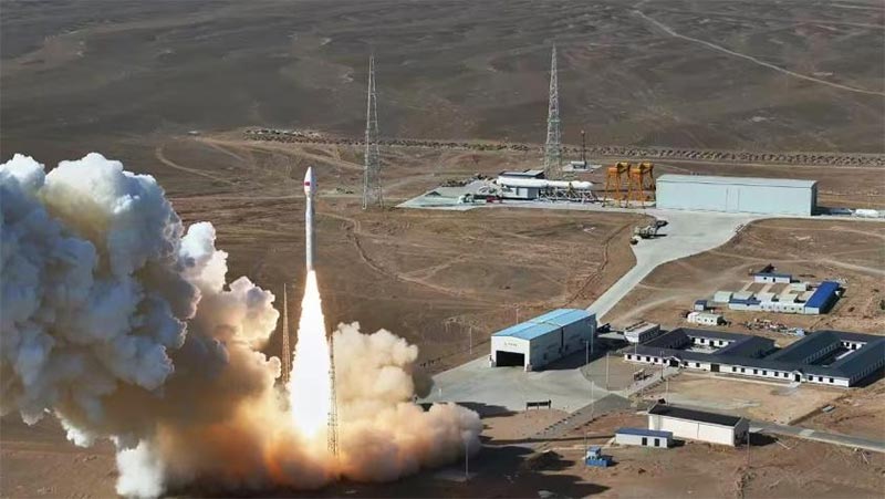
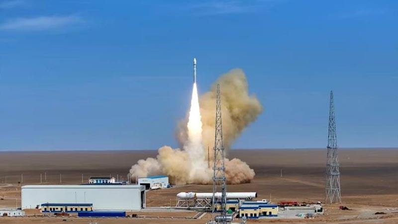
Cas-space Rocket Launch Project

Project ReferenceProject Reference

Cas-space Rocket Launch ProjectCas-space Rocket Launch Project

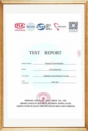
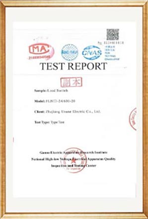
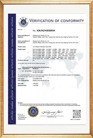
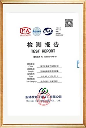
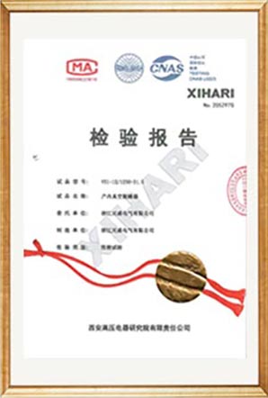
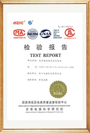
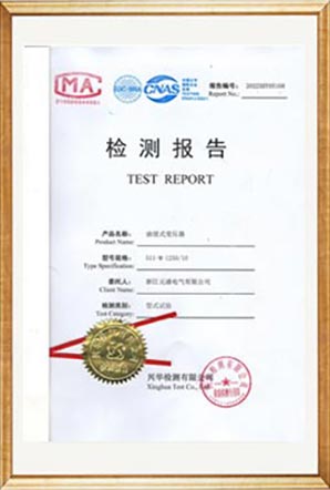
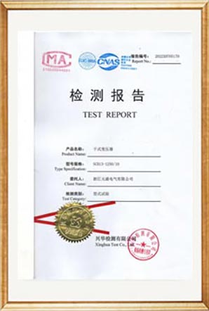
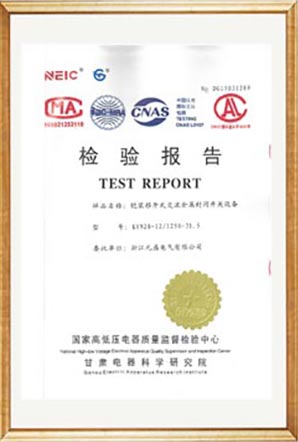
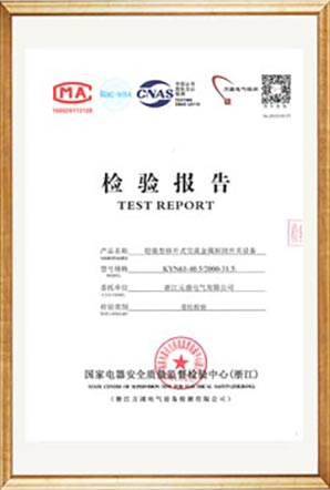
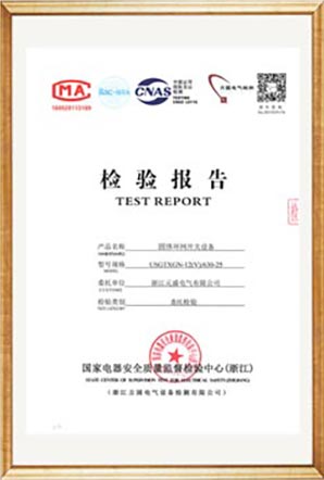
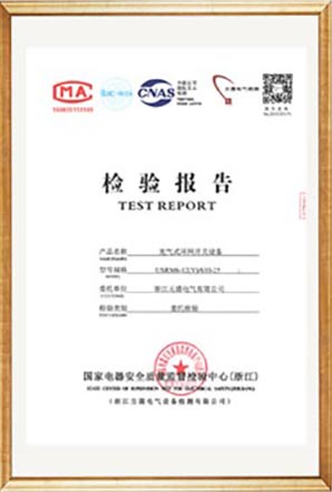
Test Report

Test ReportTest ReportTest ReportTest ReportTest ReportTest ReportTest ReportTest ReportTest ReportTest ReportTest ReportTest ReportTest ReportTest ReportTest Report

FAQs

1. Are you factory or trading company?

Factory, we can guarantee our price is reasonable and competitive.

2. When can I have the price?

Usually we quote within 24 hours after receiving your inquiry.

3. Can we print our logo and company name on products?

Yes, of course, we accept OEM.

4. What is the lead time?

The lead time depends on the quantities ordered, normally within 15-20 days after receiving the payment.

5. How's your quality control process?

All products will be inspected starting from accessories, and will be carried out with routine tests before leaving our factory.

6. How to solve the quality problems after sales?

Take photos or video of the quality problems and send to us for our checking and confirming, and we will make a satisfied solution for you within 1-3 days.

7. What's the warranty time?

12 months from shipping date.

8. Why choose us

● We are specialized in the field for more than 14 years, and has a well experienced R&D team taking the design and development work for each project based on customer's special demands.
● We have extremely strict QC procedure from components to finished products.
● Steady production period within 15-20 days.
● We have full set of test reports for products.
● One step solution provided.

Hot Tags: 630A SF6 Ring Main Unit, SF6 Gas Insulated Ring Main Unit, Ring Main Unit Manufacturer
Send Inquiry
Contact Info
If you have any inquiry about a quotation or cooperation, please feel free to email or use the following inquiry form. Our sales representative will contact you within 24 hours.
X
We use cookies to offer you a better browsing experience, analyze site traffic and personalize content. By using this site, you agree to our use of cookies. Privacy Policy
Reject Accept