Products

Products

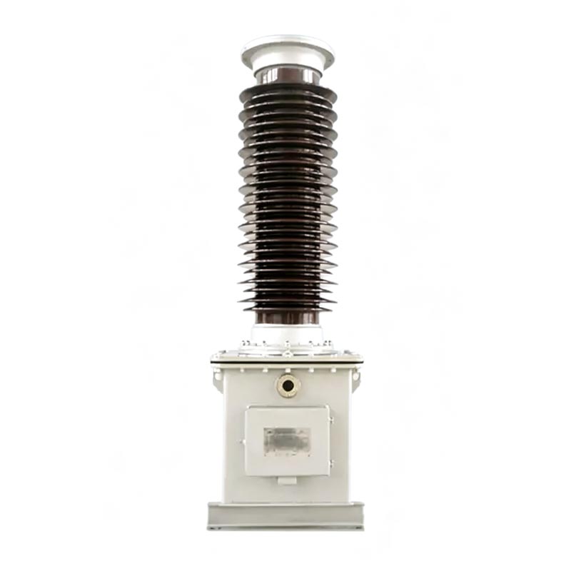
110 kV Pt Voltage Transformer
  • 110 kV Pt Voltage Transformer110 kV Pt Voltage Transformer
  • 110 kV Pt Voltage Transformer110 kV Pt Voltage Transformer
  • 110 kV Pt Voltage Transformer110 kV Pt Voltage Transformer

110 kV Pt Voltage Transformer

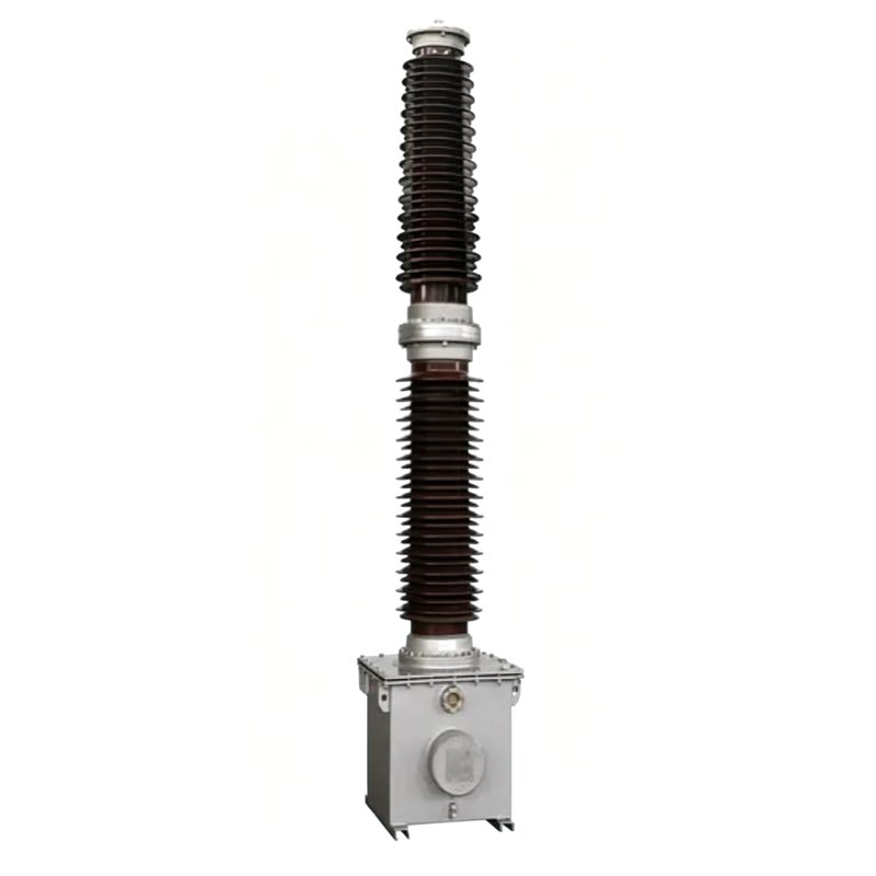
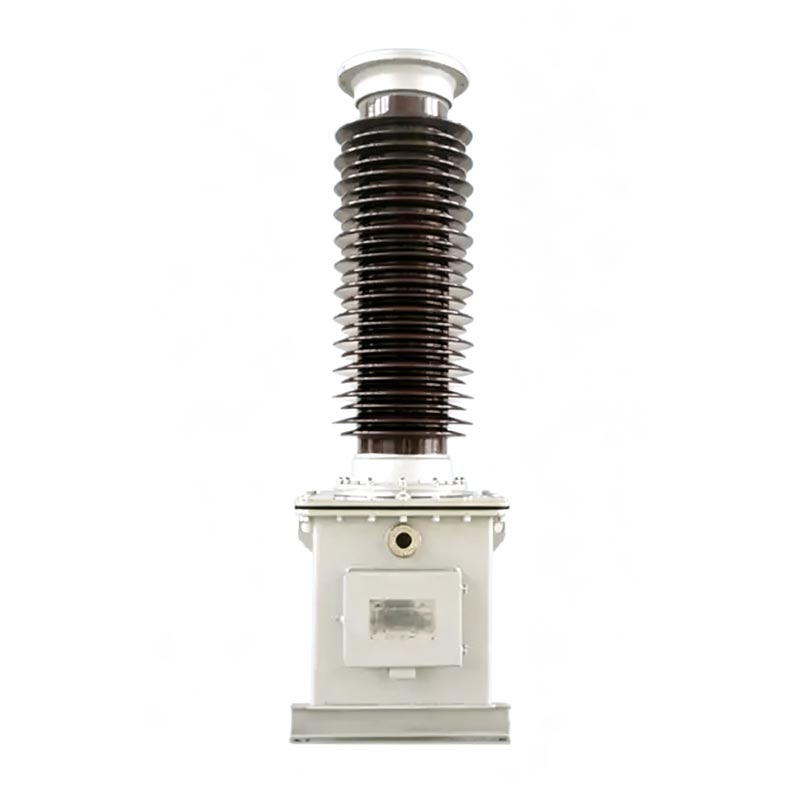
The Usune TYD series 110 kV Pt Voltage Transformer is an outdoor single-phase oil-immersed high-voltage power equipment independently developed and manufactured by a leading manufacturer in China's power transmission and transformation industry. The product conforms to the national GB/T series standards, is compatible with 50/60Hz AC power systems, and can accurately step down 110kV high voltage to 100/√3V or 100V standard low voltage, meeting the needs of power grid energy metering, voltage measurement, relay protection, and synchronization verification. It can also be used as a coupling capacitor for power line carrier communication. As a professional power equipment supplier, Usune relies on a standardized factory production system and stringent quality inspection processes to ensure the long-term safe and stable operation of its equipment.

The Usune TYD series 110 kV Pt Voltage Transformer is a high-performance capacitive voltage transformer specifically designed for 110kV high-voltage power grids. The product adopts the capacitive voltage division principle and a fully sealed oil-immersed structure, avoiding the shortcomings of traditional transformers such as large size and weak anti-interference, and possesses excellent pollution resistance, low-temperature tolerance, and wind resistance. This equipment integrates measurement, protection, and carrier communication coupling functions, and is a core supporting device for the intelligent operation and maintenance of 110kV power transmission and transformation systems.

The 110 kV Pt Voltage Transformer strictly adheres to national standards GB/T20840.1-2010, GB/T20840.5-2013, and GB/T19749-2005. Its design, production, and testing processes are standardized, and all performance parameters meet the preventive testing specifications for power equipment.

110 Kv Pt Vt Voltage Transformer110 Kv Pt Vt Voltage Transformer

110 Kv Pt Vt Voltage Transformer

110 Kv Pt Vt Voltage Transformer

Capacitor Voltage Transformer

TYD-35 (66, 110/220)kV-0.01 (0.02)

General Instructions

110 Kv Pt Vt Voltage Transformer

Product Model Explanation

- TYD: Special code for capacitive voltage transformers
- 110/3: Rated phase voltage of the system to which it is compatible is 110kV
- 0.02: Rated capacitance of the capacitive voltage divider is 0.02μF
- Suffix characteristic code: H - Anti-pollution type; G - High-altitude type (suitable for altitudes above 2000m); F - Suitable for neutral point non-effectively grounded systems

Example: TYD110/3-0.02FH represents a capacitive voltage transformer suitable for 110kV neutral point non-effectively grounded power grids, with a rated capacitance of 0.02μF and a high anti-pollution rating.

Core Structure Components

1. Capacitive Voltage Divider

Composed of coupling capacitors and voltage dividing capacitors stacked together. Multiple sets of capacitor elements are connected in series inside the porcelain bushing. It uses a high-quality thin film and capacitor paper composite dielectric and is vacuum impregnated with high-quality insulating oil. The equipment has a fully sealed structure with a built-in oil compensation device to maintain stable internal pressure, prevent oil leakage, eliminate the need for on-site sampling, effectively isolate external moisture and impurities, and ensure stable insulation performance.

2. Electromagnetic Device

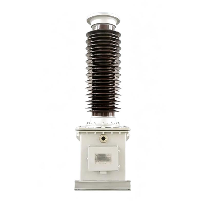
The 110 kV Pt Voltage Transformer is entirely sealed within an oil-filled steel tank (which also serves as a capacitor base), including an intermediate transformer, a compensating reactor, and a fast-saturation reactor damper. It is pre-assembled with the low-voltage dividing capacitor before leaving the factory. The electromagnetic unit and the capacitor divider's oil circuit are completely isolated, ensuring no interference and stable operation. Secondary wiring and carrier wave terminals are centrally located in a junction box on the side wall of the tank, clearly labeled for easy on-site wiring and maintenance.

Core Product Functions

1.Energy Metering and Voltage Monitoring

Accurately steps down the output to provide a standard low-voltage signal, offering reliable data support for power grid energy metering and real-time voltage monitoring.

2.Power Grid Relay Protection

Equipped with relay protection and automatic control equipment, it enables power grid fault identification, synchronization verification, and line protection, preventing equipment damage and power grid accidents caused by voltage anomalies.

3.Carrier Communication Coupling

Serves as a dedicated coupling capacitor for power line carrier communication, providing a stable signal channel for power grid data transmission and remote operation and maintenance.

Technical Parameters and Operating Environment

1. Core Technical Parameters

- Compatible Operating Conditions: 50/60Hz AC power system
- Secondary Output Voltage: 100/√3V, 100V (standard specifications)
- Dielectric Loss Tangent: ≤0.002
- Capacitor Error: Not exceeding ±2% of nameplate rating
- Insulation Resistance: ≥500MΩ (measured with a 2500V megohmmeter)
- Overvoltage Operation Capability: Long-term operation at 1.2 times rated voltage; short-term operation at 1.5 times rated voltage for 30 seconds; Type F can operate continuously for 8 hours at 1.9 times rated voltage

2. Applicable Environmental Conditions

- Operating Temperature: -40℃~+45℃ (customizable for special conditions)
- Maximum Wind Speed Resistance: 150km/h
- Applicable Altitude: ≤2000m (high-altitude models available upon request)
- Maximum Icing Thickness: 10mm
- Anti-pollution rating: Standard Class D (creepage distance ≥ 43.3 mm/kV), optional Class E (creepage distance ≥ 53.7 mm/kV)

Engineering Application Case

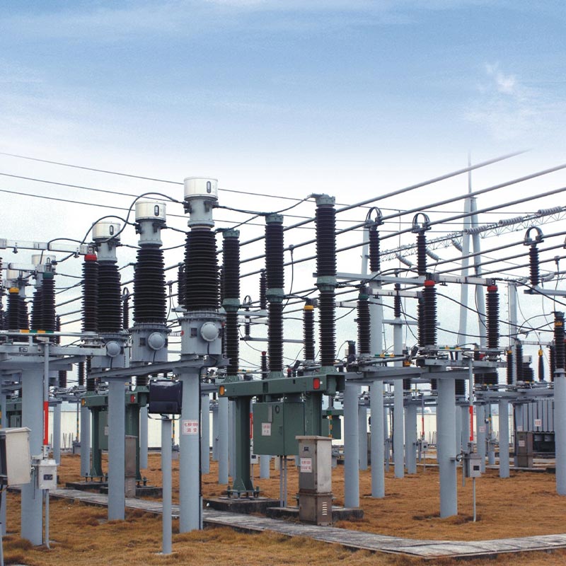
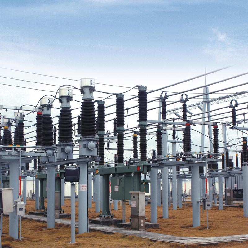
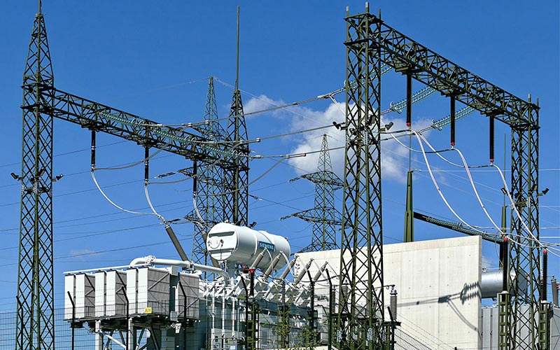
The Usune TYD110/3-0.02FH anti-pollution 110 kV Pt Voltage Transformer was successfully applied to an outdoor renovation project of a 110kV regional substation in Zhejiang Province. This substation serves surrounding industrial parks and residential areas, requiring extremely high power supply stability and equipment reliability. Located in a coastal area with high humidity, high salt spray, and heavy pollution, and with frequent sea breezes, the project demands stringent anti-pollution, anti-corrosion, and anti-aging performance from high-voltage equipment.

The equipment was hoisted, installed, and commissioned strictly according to the manufacturer's specifications before being put into operation. Two years of on-site operation and maintenance and regular testing data show that core parameters such as equipment capacitance and dielectric loss consistently meet national standards, with no issues such as oil leakage, abnormal noise, or parameter drift. Its superior anti-fouling and anti-corrosion structure effectively resists the corrosion of coastal salt spray and humid air, avoiding common faults such as insulation aging and voltage fluctuations in traditional instrument transformers. It stably completes power metering, voltage monitoring, and carrier communication coupling, ensuring continuous and safe power supply to the substation, and fully verifying the product's stability and adaptability under harsh outdoor conditions.

Installation and Maintenance Specifications

1.Installation Points

The equipment is shipped as a complete set of capacitor voltage divider + electromagnetic device. Installation must strictly adhere to the nameplate numbers; arbitrary mixing and replacement are strictly prohibited. For equipment hoisting, the dedicated lifting holes for the electromagnetic unit oil tank must be used; direct hoisting of capacitor porcelain bushings is prohibited. The foundation is fixed with M20 high-strength bolts, and the overall installation tilt angle is ≤2/1000mm to ensure stable equipment operation.

Key Wiring Requirements: Damper terminals d1 and d2 must be reliably connected; open circuits are strictly prohibited. When not connected to carrier equipment, N and X terminals must be reliably short-circuited. During equipment operation, terminal X must be directly and reliably grounded to prevent high voltage from entering the secondary enclosure, damaging the equipment, and endangering personal safety.

2.Operation and Maintenance & Safety Precautions

The equipment features a fully sealed oil-immersed structure, ensuring stable performance and eliminating the need for routine oil sampling and testing. Routine maintenance only requires periodic checks of the equipment's sealing condition, terminal tightness, and troubleshooting for abnormal noises, secondary voltage anomalies, and sudden voltage spikes in the open delta connection. Unauthorized disassembly of the equipment's fastening bolts and sealing structure is strictly prohibited. The capacitor divider and electromagnetic device must not be disassembled without the manufacturer's permission. After the equipment is scrapped, it must be handed over to the local environmental protection department for centralized and harmless disposal to prevent environmental pollution.

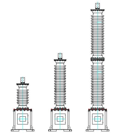
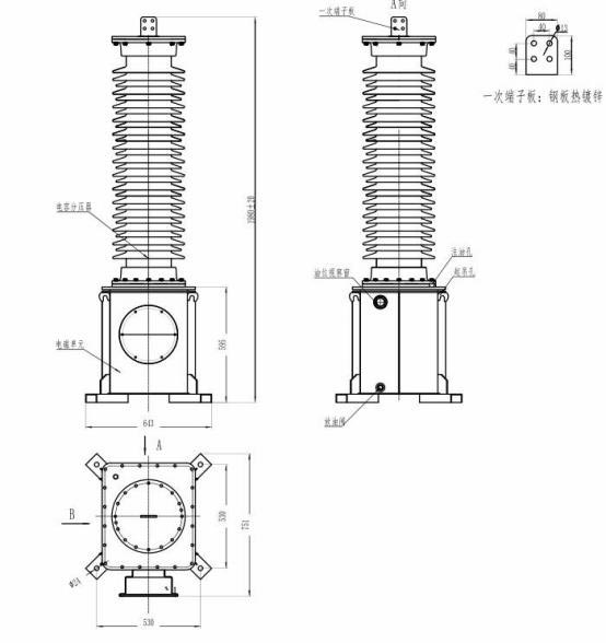
Product dimensions.

110 Kv Pt Vt Voltage Transformer

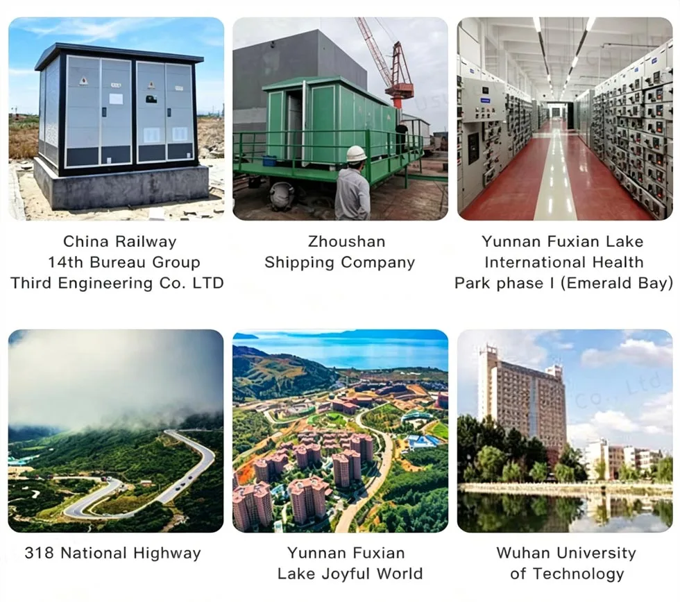
Project Reference

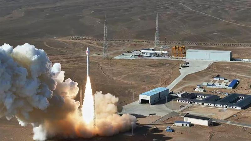
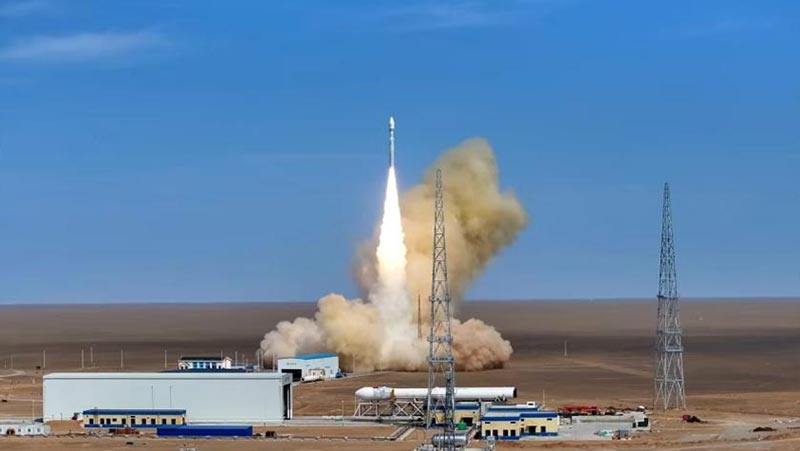
Cas-space Rocket Launch Project

Project ReferenceProject Reference

Cas-space Rocket Launch ProjectCas-space Rocket Launch Project

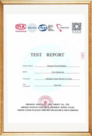
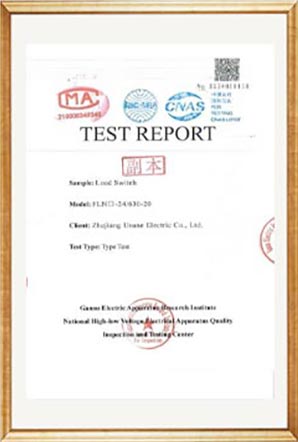
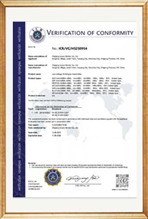
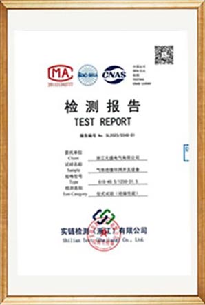
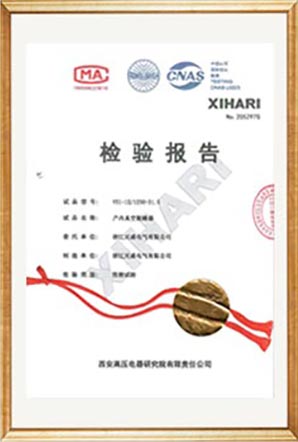
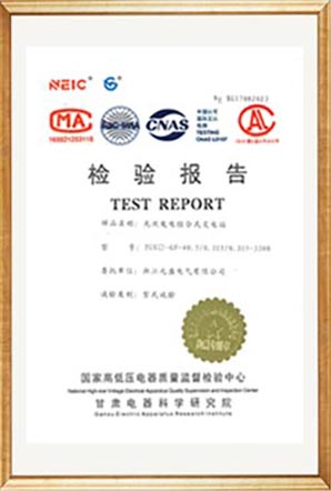
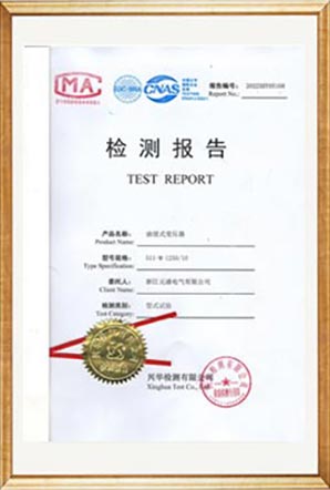
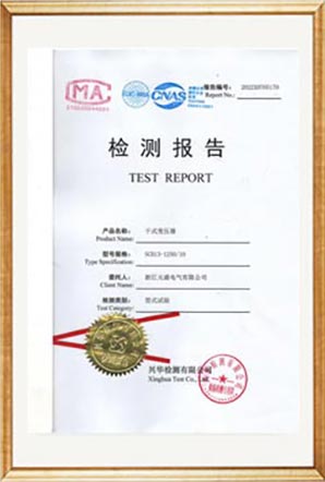
Test Report

Test ReportTest ReportTest ReportTest ReportTest ReportTest ReportTest ReportTest ReportTest ReportTest ReportTest ReportTest ReportTest ReportTest ReportTest Report

FAQ

Q1: What are the differences between the H, G, and F suffix models of the Usune 110 kV Pt Voltage Transformer, and what scenarios are they suitable for?

H is the pollution-resistant type, suitable for coastal and heavily polluted industrial scenarios, with enhanced creepage distance and corrosion resistance; G is the high-altitude type, optimized for areas above 2000m altitude, suitable for low-voltage and strong ultraviolet environments; F is a dedicated type for neutral point non-effective grounding, with stronger overvoltage tolerance, suitable for corresponding power grid systems. The appropriate model can be selected based on the project's geographical environment and power grid system.

Q2: Why is it strictly forbidden to disconnect terminals D1, D2, and N-X during equipment operation?

D1 and D2 are damper terminals. Opening them will cause damper failure, triggering internal overvoltage surges and causing permanent damage to capacitors and electromagnetic units. When no carrier equipment is connected, disconnecting terminals N-X will allow high voltage to enter the secondary junction box, burning out secondary monitoring and protection equipment and causing a safety accident. The reliability of terminal connections must be checked before commissioning the equipment.

Q3: Does the Usune 110 kV Pt Voltage Transformer require periodic oil sampling and testing during operation?

No, periodic oil sampling and testing is not required. The electromagnetic unit operates at low voltage, and a complete set of sealing and performance tests has been completed before leaving the factory, ensuring reliable sealing performance. On-site sampling will disrupt the internal pressure balance of the equipment, leading to potential problems such as oil level drop, moisture intrusion, and insulation deterioration. Routine checks only need to verify the integrity of the seals and the stability of electrical parameters. If parameters are abnormal, contact the manufacturer for specialized testing.


Hot Tags: 110 kV Pt Voltage Transformer supplier, 110 kV VT manufacturer, 110 kV voltage transformer factory
Send Inquiry
Contact Info
If you have any inquiry about a quotation or cooperation, please feel free to email or use the following inquiry form. Our sales representative will contact you within 24 hours.
X
We use cookies to offer you a better browsing experience, analyze site traffic and personalize content. By using this site, you agree to our use of cookies. Privacy Policy
Reject Accept